ATL P1000 Series Tape Library User’s Guide 6221101-03 Ver. 3, Rel.
ATL P1000 Series User’s Guide, 6221101-03, Ver. 3, Rel. 0, September 1999. Printed in the USA. ATL Products, Inc. provides this publication “as is” without warranty of any kind, either express or implied, including but not limited to the implied warranties of merchantability or fitness for a particular purpose. ATL Products, Inc. may revise this publication from time to time without notice. COPYRIGHT STATEMENT Copyright 1999 by ATL Products, Inc. All rights reserved.
NOTICE FOR USA AND CANADA ONLY If shipped to USA, use the UL LISTED power cord specified below for 100-120 V operation. If shipped to Canada, use the CSA CERTIFIED power cord specified below for 100-120V operation. Plug Cap Parallel blade with ground pin (NEMA 5-15P configuration) Cord Socket IEC 320 connector rated 250V 15A Cord Type: SJT, three 16 AWG or 18 AWG wires Length Maximum 15 feet (4.5m) Rating Minimum 10 A, 125 V ATTENTION LIRE LA REMARQUE DANS LE MODE D'EMPLOI.
Achtung! Die Bandbibliothek enthält eine Lithiumbatterie. Der Halbleiter Dallas Semiconductor DS1230AB-200 auf dem RoboterController enthält eine Lithiumbatterie. Lithium gilt als Schadstoff. Bei der Entsorgung dieser Batterie alle entsprechenden kommunalen, staatlichen und bundesweiten Vorschriften beachten! Attenzione La libreria a nastro magnetico contiene una batteria al litio. Il semiconduttore Dallas Semiconductor DS1230AB-200 sulla scheda controller robotic contiene una batteria al litio.
Contents 0 Contents Preface Chapter 1 Library Description......................................................................................1 Configuration Options..................................................................................3 Library Elements ...........................................................................................5 Robotics Operation........................................................................................7 Operator-Accessible Components .........
Contents SCSI Cabling Examples ....................................................................... 35 Turning On the Library.............................................................................. 39 Configuring and Testing the Library ....................................................... 40 Chapter 3 Basic Operations ........................................................................................ 41 Using the GUI.........................................................................
Contents Initializing Nonvolatile Information ........................................................81 Changing Passwords ..................................................................................83 Chapter 6 Troubleshooting .........................................................................................85 Start-up Problems........................................................................................86 GUI Problems...............................................................
Contents viii ATL P1000 Series User’s Guide
Figures 0 Figures Figure 1 P1000 Front View, Stand-alone Library..................................1 Figure 2 P1000 Front View, Rack-mount Library .................................2 Figure 3 P1000 Library, Back View.........................................................4 Figure 4 Library Elements........................................................................6 Figure 5 P1000 Front Panel ......................................................................
Figures Figure 29 GUI: Initial Screen ................................................................... 42 Figure 30 Navigating through the GUI Screens ................................... 44 Figure 31 GUI Screens .............................................................................. 45 Figure 32 Overview Screen...................................................................... 46 Figure 33 Overview Screen with Expanded Tape Drive Status......... 47 Figure 34 Tapes Screen.......................
Tables 0 Tables Table 1 Related Documentation ........................................................ xiv Table 2 Bar Code Label Specifications................................................30 Table 3 Sample Library Configuration...............................................40 Table 4 Vertical Bar Buttons and Indicators ......................................43 Table 5 Horizontal Bar Buttons ...........................................................44 Table 6 GUI Screens ...................
Tables xii ATL P1000 Series User’s Guide
Preface 0 Preface Audience Purpose 0 0 This guide was written for operators of the P1000 library. This guide provides procedures for unpacking, installing, operating, and troubleshooting the basic P1000 library with a standard SCSI host interface. The optional Fibre Channel capabilities are detailed in a separate series of documents (see “Related Documents” on page xiv).
Preface Notational Conventions 0 This manual uses the following conventions: 0 Caution: Cautions indicate potential hazards to equipment and are included to prevent damage to equipment. Note: Notes emphasize important information related to the main topic. Warning: Warnings indicate potential hazards to personal safety and are included to prevent injury.
Preface SCSI-2 Specification 0 The SCSI-2 communications specification is the proposed American National Standard for information systems, dated March 9, 1990. Copies may be obtained from: Global Engineering Documents 15 Inverness Way, East Eaglewood, CO 80112 (800) 854-7179 or (303) 397-2740 Contacts 0 This section provides contact information for ATL Products. ATL Products Corporate Headquarters 0 To order documentation for the ATL P1000, contact: ATL Products, Inc.
Preface xvi ATL P1000 Series User’s Guide
Chapter 1 Library Description Chapter 1 Library Description 1 The ATL P1000 is an automated tape library system. When fully configured, the P1000 consists of four tape drives and 30 cartridges. The maximum storage capacity of the P1000 is 1050 GB (up to 2100 GB compressed), based on 30 cartridges at 35 GB each (up to 70 GB compressed). The P1000 library is shipped in either a stand-alone (see figure 1) or rack-mount configuration (see figure 2). The stand-alone P1000 is set on casters.
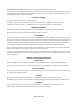
Chapter 1 Library Description Figure 2 P1000 Front View, Rack-mount Library Rack (not included) Key lock GUI Bulk pack door Load pack door Power switch Load port 2 ATL P1000 Series User’s Guide
Chapter 1 Library Description Configuration Options Configuration Options 1 As shown in figure 1 and figure 2, the P1000 library is available in stand-alone and rack-mount configurations. Other library options include: • the number of tape drives The P1000 holds one to four tape drives. • high-density or low-density tape configuration The high-density configuration consists of up to 30 tape cartridges: 9 in the back storage bins, 5 in the front storage bins, 8 in the load pack, and 8 in the bulk pack.
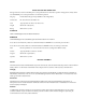
Chapter 1 Library Description Configuration Options Figure 3 P1000 Library, Back View Host port, DIAG port, and library printed circuit boards Tape drive SCSI connectors Bus connector Power connector 4 ATL P1000 Series User’s Guide
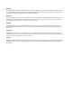
Chapter 1 Library Description Library Elements Library Elements 1 The P1000 has the following elements (see figure 4 on page 6): • storage bins • nine-pack fixed storage array (bins 0 to 8) (in high-density configuration only) • four-pack fixed storage array (bins 9 to 12) (in high-density configuration only) • one-pack fixed storage array (bin 13) (in high-density configuration only) • bulk pack (bins 14 to 21) • load pack (bins 22 to 29) Note: In the low-density configuration, the P1000 stor
Chapter 1 Library Description Library Elements Figure 4 Library Elements Bulk pack Four-pack array3 Bin 9 Bin 10 Bin 11 Bin 12 Load port Load 0 One-pack array3 Bin 13 Bin 14 Bin 15 Bin 16 Bin 17 Bin 18 Bin 19 Bin 20 Bin 21 Bin 0 Bin 1 Bin 2 Bin 22 Bin 23 Bin 24 Bin 25 Bin 26 Bin 27 Bin 28 Bin 29 Drive 0 Drive 2 Bin 3 Bin 4 Bin 5 Bin 6 Bin 7 Bin 8 Nine-pack array3 Drive 1 Drive 3 Tape drives2 Load pack1 1 When configured as an import/export device, load pack bins are numbered “Load 1” to
Chapter 1 Library Description Robotics Operation Robotics Operation 1 Library robotics consist of the following components: • gripper mechanism/bar code reader • vertical actuator • horizontal actuator • extension actuator The vertical and horizontal actuators move the gripper into position to pick and place tape cartridges. The horizontal actuator also rotates the gripper 180 degrees, allowing the gripper to pass cartridges between the front storage bins and the back storage bins or tape drives.
Chapter 1 Library Description Operator-Accessible Components Operator-Accessible Components 1 The following P1000 components are operator-accessible: • front panel • load and bulk packs • back panel • tape drives The following sections describe each of these components. Front Panel Figure 5 P1000 Front Panel 1 The front panel consists of the GUI, the front doors and key lock, the power switch, and the load port (see figure 5).
Chapter 1 Library Description Operator-Accessible Components Horizontal bar Figure 6 GUI: Initial Screen Back Forward Home ATL P R O D U C T S System Off-line Standby Vertical bar Load Port Load Pack Overview Tapes Operator ATL Main display area P R O D U C T S P 1 0 0 0 U Stop The GUI screen consists of: • a horizontal bar (at the top of the screen) • a vertical bar (at the left side of the screen) • a main display area The main display area contains a series of screens with status, co
Chapter 1 Library Description Operator-Accessible Components The front doors lock to prevent unauthorized access to the P1000. To unlock and open the doors: Procedure 1 If the library is on-line, press the Standby button on the GUI. The system status indicator above the Standby button changes to indicate that the library is in Standby mode. 2 Use the key to unlock the load pack door. 3 Press the Load Pack button on the GUI. This prepares the library for load pack removal.
Chapter 1 Library Description Operator-Accessible Components Back Panel 1 The back panel of the P1000 (see figure 8) has the following components: • SCSI ports • RS-232C diagnostic (DIAG) port • power connector • drive access (hot swap) • air filters These components provide the P1000 with power and communication links to external systems.
Chapter 1 Library Description Operator-Accessible Components Tape Drives 12 1 The P1000 holds up to four tape drives. When fewer than four tape drives are installed, the tape drives must occupy consecutive drive bays, beginning with drive bay 0 (see figure 4 on page 6).
Chapter 2 Installing the P1000 Library Chapter 2 Installing the P1000 Library 2 This chapter explains how to install the stand-alone and rack-mount configurations of the P1000 library.
Chapter 2 Installing the P1000 Library Site Requirements Site Requirements 2 When selecting an installation site for the P1000 library, consider the following requirements: Floor Space 2 • floor space • floor clearance • overhead clearance • floor strength and inclination • power and grounding • environmental factors Figure 9 shows the floor space requirements of the stand-alone P1000. Figure 9 Floor Space Requirements, Stand-alone Library 17.5 in. (45 cm) 24 in. (61 cm) 29.5 in.
Chapter 2 Installing the P1000 Library Site Requirements Figure 10 shows the floor space requirements for the rack-mount P1000. Figure 10 Floor Space Requirements, Rack-mount Library 24 in. (61 cm) each side 24 in. (61 cm) Front 17.5 in. (45 cm) Back 19-inch rack Library (extended from rack) 24 in. (61 cm) 30 in. (76.2 cm) Floor Clearance Floor Strength and Inclination 2 2 The stand-alone P1000 has a floor clearance of 0.75 in. (1.9 cm).
Chapter 2 Installing the P1000 Library Site Requirements Power Inlet 2 The power inlet is an IEC-320 connector (see figure 11). For international applications, replace the power cord with a harmonized 3 x 1.0 mm2 power cord approved by the country where used. Ground Figure 11 AC Power Receptacle ~100V to 120V / ~200V to 240V 6A/3A 50Hz/60Hz IEC-320 Type Line Neutral Rack Current Rating Consideration 2 Consider the current rating of the rack before installing more than one P1000 library.
Chapter 2 Installing the P1000 Library Unpacking the P1000 Unpacking the P1000 2 This section explains how to receive and unpack the P1000. Note: If you have already unpacked the library following the procedures in the ATL P1000 Series Unpacking Instructions, skip ahead to “Preparing and Inserting Tape Cartridges” on page 30.
Chapter 2 Installing the P1000 Library Unpacking the P1000 Figure 12 Unloading Space Requirements, Stand-alone Library Library Pallet Pallet ramp Unloading area (minimum) 33 in. (84 cm) 30 in. (76 cm) 18 in. (46 cm) Uncrating the Library 97 in. (2.5 m) 2 To uncrate the P1000 library: Note: Be careful not to damage the shipping materials while uncrating the library. Save all packaging materials for possible future shipment of the library.
Chapter 2 Installing the P1000 Library Unpacking the P1000 Procedure (continued) 2 Remove these items from the carton and set them aside. 3 Remove all foam supports from inside the carton (see figure 13 on page 19 and figure 14 on page 20).
Chapter 2 Installing the P1000 Library Unpacking the P1000 Accessories tray Figure 14 Uncrating the Rack-mount Library Slide assembly Foam supports Library Clips Procedure (continued) 4 Release the four clips that secure the carton to the pallet. To release a clip, pinch the center tabs of the clip firmly together and pull on the tabs. 5 Checking the Contents 20 2 Lift the carton off of the pallet and set it aside.
Chapter 2 Installing the P1000 Library Unpacking the P1000 Installing the Slide Assembly in the Rack Removing the Library from the Pallet 2 2 If you are installing a rack-mount library, install the slide assembly in the rack before proceeding to the next section, “Removing the Library from the Pallet.” See appendix B for slide assembly installation instructions.
Chapter 2 Installing the P1000 Library Unpacking the P1000 Figure 15 Removing the Foam Supports, Stand-alone Library Foam supports Procedure (continued) 3 Attach the ramp to the pallet using fastener strips (see figure 16). 4 Make any necessary preparations for moving the library. This may involve clearing a path to the installation site, unlocking doors, and placing mats over carpeted areas. 5 Carefully roll the library down the ramp.
Chapter 2 Installing the P1000 Library Unpacking the P1000 Procedure (continued) 6 Detach the ramp and place it on top of the pallet. 7 Roll the library to the installation site. 8 Save the shipping carton, bag, foam supports, ramp, and pallet for future use. These items are required to package the library for reshipment. Removing a Rack-mount Library from the Pallet 2 Note: The instructions in this section assume you have already installed the slide assembly in the rack.
Chapter 2 Installing the P1000 Library Unpacking the P1000 Figure 17 Lifting the Rack-mount Library from the Pallet Library Foam supports Shipping bag Pallet Procedure (continued) 4 24 Place the library on the fully extended slide assembly tray (see figure 18).
Chapter 2 Installing the P1000 Library Unpacking the P1000 Figure 18 Placing the Library on the Slide Assembly Tray Inner channel lock Screws Procedure (continued) 5 Secure the library to the slide tray, using six screws from the accessories kit (see figure 18). 6 Verify that, when the slide assembly is fully extended, there is adequate clearance around the library to access the back panel and remove the library enclosure.
Chapter 2 Installing the P1000 Library Unpacking the P1000 Figure 19 Locking the Slide Tray in the Rack Retma rail Locking bracket Procedure (continued) 9 Save the shipping carton, bag, foam supports, and pallet for future use. These items are required to package the library for reshipment.
Chapter 2 Installing the P1000 Library Unpacking the P1000 Removing the Internal Packing Materials 2 This section explains how to remove the internal packing materials that protect the library during shipping and installation. Caution: Before removing the internal packing materials, verify that the library is at its final installation site. Moving the library without these materials in place may damage the library.
Chapter 2 Installing the P1000 Library Unpacking the P1000 Figure 20 Removing the Load and Bulk Packs Handles Removing the Shipping Restraint 2 Note: The shipping restraint that protects the extension axis assembly is attached to the bottom drive shelf and fits over the supports for the load and bulk packs. To remove the shipping restraint: Procedure 1 Grasp the front edge of the shipping restraint and carefully push inward at both corners while lifting it up at an angle (see figure 21).
Chapter 2 Installing the P1000 Library Unpacking the P1000 Procedure (continued) 3 Raise the extension axis assembly and remove the foam block beneath it. 4 Lower the extension axis assembly to its normal position on the floor of the library. Note: Retain the original shipping container and shipping bag, pallet, ramp, accessories tray, and all packing materials for future use.
Chapter 2 Installing the P1000 Library Preparing and Inserting Tape Cartridges Preparing and Inserting Tape Cartridges 2 This section explains how to insert tape cartridges into the P1000 library during initial installation.
Chapter 2 Installing the P1000 Library Preparing and Inserting Tape Cartridges Min.a Max. Average Message length 6.00 6.00 6.00 Traditional tests PASS PASS PASS IN TOL IN TOL IN TOL OK OK OK Print quality grade B C C Formatting checks PASS PASS PASS Sample Number Bar growth PCS a. All bar code parameters should fall within the Min./Max. values when tested using a PSC Quick Check 500 bar code tester. Figure 22 Bar Code Label Dimensions .
Chapter 2 Installing the P1000 Library Preparing and Inserting Tape Cartridges Setting the Write-protect Switch 2 The write-protect switch controls whether the tape cartridge is write-protected or write-enabled: • Write-protecting a cartridge protects the data it contains from being erased or overwritten. To write-protect a cartridge, move the write-protect switch to the left (see figure 24). An orange tab appears above the switch.
Chapter 2 Installing the P1000 Library Preparing and Inserting Tape Cartridges Procedure (continued) 2 Remove the load and bulk packs from the library (see figure 20 on page 28): a Grip the load pack handles and squeeze them together. This releases the latches securing the load pack. b Still holding the load pack handles, pull the load pack forward and out of the library. c Repeat steps 2a and 2b to remove the bulk pack. 3 Set both packs aside.
Chapter 2 Installing the P1000 Library Preparing and Inserting Tape Cartridges Placing Tape Cartridges in the Load and Bulk Packs To place cartridges in the load and bulk packs: 2 Note: This procedure assumes that you have already removed the load and bulk packs. If not, remove the load and bulk packs, referring to steps 2a through 2c on page 33. Procedure 1 Load eight cartridges into each pack.
Chapter 2 Installing the P1000 Library Connecting Host Computers Connecting Host Computers 2 You are now ready to connect one or more host computers to the library. You can connect up to five host computers on separate SCSI busses. Note: If your library is equipped with the Prism FC210 Router, disregard this section. Instead, see the ATL PrismFC210 Router Addendum (PN 6331101).
Chapter 2 Installing the P1000 Library Connecting Host Computers In the single-host configuration (see figure 26), the host computer is connected to the host connector on the rear panel of the library. Since there is only one SCSI bus, use all of the SCSI cables from the accessories kit to daisy-chain the library to each of the tape drives. Figure 26 Single-Host SCSI Configuration P1000 back panel Host connector 21 in. (53 cm) SCSI cable 15 in. (38 cm) SCSI cable 7 in.
Chapter 2 Installing the P1000 Library Connecting Host Computers In the two-host configuration (see figure 27), host 1 is connected to the library and daisy-chained to tape drives 0 and 1 (upper drives). Host 2 is connected to tape drive 3 and daisy-chained to tape drive 2 (lower drives). The first SCSI bus is terminated at drive 0; the second is terminated at drive 2.
Chapter 2 Installing the P1000 Library Connecting Host Computers In the five-host configuration (see figure 28), five hosts are connected to the library, requiring five SCSI terminators.
Chapter 2 Installing the P1000 Library Turning On the Library Turning On the Library 2 To turn on the library: Procedure 1 Verify that: • all internal packaging is removed • the front doors and load port are closed • the library enclosure is installed • all back panel connections are secure 2 At the front panel, set the power switch on. 3 After several seconds, verify that the touch screen graphical user interface (GUI) comes on.
Chapter 2 Installing the P1000 Library Configuring and Testing the Library Configuring and Testing the Library When you finish installing the library, make any desired changes to the library configuration and then calibrate the library and test its functionality. Table 3 shows a sample library configuration.
Chapter 3 Basic Operations Chapter 3 Basic Operations 3 This chapter describes the following basic library operating procedures: • using the touch screen graphical user interface (GUI) • GUI components • GUI screens • obtaining library status • changing the GUI security level • performing manual operations • turning the library on and off • placing the library on- or off-line • inserting tape cartridges • opening the library doors • manually ejecting a tape cartridge For more advance
Chapter 3 Basic Operations Using the GUI Using the GUI 3 At start-up, the GUI displays the following screen (see figure 29). Horizontal bar Figure 29 GUI: Initial Screen Back Forward Home ATL P R O D U C T S System Off-line Standby Vertical bar Load Port Load Pack Overview Tapes Operator ATL Main display area P R O D U C T S P 1 0 0 0 U Stop From this screen, you can access controls to configure and operate the library.
Chapter 3 Basic Operations Using the GUI Vertical Bar 3 Table 4 describes each of the buttons and indicators on the vertical bar. Table 4 Vertical Bar Buttons and Indicators Button/Indicator Description Company logo This area of the screen displays the ATL logo. Pressing the logo causes the GUI to display an “About ATL” screen. System status indicator The system status indicator shows the current state of the library and displays important messages relating to library operation.
Chapter 3 Basic Operations Using the GUI Horizontal Bar 3 Table 5 describes each of the buttons on the horizontal bar. Table 5 Horizontal Bar Buttons Button Description Back button Pressing this button moves you backward screen-by-screen through previously selected screens. Forward button Pressing this button moves you forward screen-by-screen through previously selected screens. Home button Pressing this button returns you to the initial GUI screen (see figure 29 on page 42).
Chapter 3 Basic Operations Using the GUI Table 6 describes each of the GUI screens. Table 6 GUI Screens GUI Screens Figure 31 GUI Screens 3 Screen Description Overview This screen provides an overview of the tape drives, robot activity, and load pack inventory. Tapes This screen displays the contents of the tape drives, storage bins, load packs, the gripper, and the load port. Operator This screen contains the library configuration and control functions.
Chapter 3 Basic Operations Obtaining Library Status Obtaining Library Status 3 You can obtain library status from the Overview and Tapes screens. Overview Screen 3 To open the Overview screen, press the Overview tab on the GUI.
Chapter 3 Basic Operations Obtaining Library Status Drives 3 The Drives section of the Overview screen displays the following information: • whether a tape drive has a cartridge • the bar code number of the cartridge (if a cartridge is present and the label is readable) • whether the cartridge is write-enabled or write-protected • whether compression is enabled To view more detailed information about drive status, press the Overview screen anywhere in the Drives section.
Chapter 3 Basic Operations Obtaining Library Status Load Pack 3 The Load Pack section of the Overview screen identifies the cartridges currently stored in the load pack. Press the arrow buttons at the bottom of the screen to scroll through the load pack bins and view their contents. You can also view this information using the Tapes screen. Tapes Screen 3 To open the Tapes screen, press the Tapes tab on the GUI.
Chapter 3 Basic Operations Changing the GUI Security Level Changing the GUI Security Level 3 Table 7 describes the five levels of security for the P1000 library GUI. The security level indicator at the lower left corner of the GUI indicates the current security level.
Chapter 3 Basic Operations Changing the GUI Security Level To change the security level: Procedure 1 Press the security level indicator at the lower left corner of the GUI. The GUI displays the Password screen (see figure 35).
Chapter 3 Basic Operations Performing Manual Operations Performing Manual Operations 3 This section describes procedures requiring operator intervention.
Chapter 3 Basic Operations Performing Manual Operations Placing the Library Off-line To place the library off-line: 3 Note: You must have Operator level access privileges or higher to perform this procedure (see “Changing the GUI Security Level” on page 49). Procedure Turning Off the Library 3 1 With the library turned on and the GUI indicating “System On-line,” press the Standby button on the GUI. 2 Verify that the GUI displays “System Off-line.
Chapter 3 Basic Operations Performing Manual Operations Caution: Examine all cartridges before loading them into the library or tape drive. Look for label stock or other foreign material that may be clinging to the cartridges. Procedure 1 Prepare the tape cartridge to be inserted by labeling it and setting the write-protect switch as desired (see “Preparing and Inserting Tape Cartridges” on page 30). 2 Press the Load Port button on the left side of the GUI.
Chapter 3 Basic Operations Performing Manual Operations Figure 36 Inserting a Tape Cartridge Bar code label Tape cartridge Load port Opening the Library Doors 3 Open the front doors to access a tape drive, access the load and bulk packs, or to load the library with tape cartridges. To open the library doors: Procedure 1 If the door is locked, unlock it. 2 Press the Load Pack button on the left side of the GUI. The library completes any current command and then unlocks the load pack door.
Chapter 3 Basic Operations Performing Manual Operations Manually Ejecting a Cartridge To manually eject a tape cartridge from one of the tape drives: 3 Note: You must have Import Only level access privileges or higher to perform this procedure (see “Changing the GUI Security Level” on page 49). Procedure 1 Open the library front doors (see “Opening the Library Doors” on page 54). 2 Remove the load and bulk packs from the library (see “Removing the Load and Bulk Packs” on page 27) and set them aside.
Chapter 3 Basic Operations Performing Manual Operations 56 ATL P1000 Series User’s Guide
Chapter 4 Operator Commands Chapter 4 Operator Commands 4 This chapter describes the commands on the Operator screen of the touch screen graphical user interface (GUI). Using this screen, you can: • configure the library • configure library options • move a tape cartridge • inventory the tape cartridges • calibrate the library • exercise the library • unload a tape drive • unload the load port The Operator screen is restricted to persons with Operator or Service access privileges.
Chapter 4 Operator Commands Accessing the Operator Screen Accessing the Operator Screen 4 To access the Operator screen: Procedure 1 On the GUI, press the Operator tab. The GUI displays the Enter Password screen (see figure 37). Figure 37 Enter Password Screen Back Forward Home ATL P R O D U C T S System Off-line Overview Tapes Enter Password Operator 1 2 3 4 5 6 7 8 9 0 Standby Load Port Enter Password: _ Load Pack U Stop 2 Enter Enter the Operator or Service password.
Chapter 4 Operator Commands Accessing the Operator Screen Procedure (continued) 3 Figure 38 Operator Screen If the password you entered is valid, the GUI displays the Operator screen (see figure 38). Back Forward Home ATL P R O D U C T S System Off-line Standby Overview Config.
Chapter 4 Operator Commands Configuring the Library Configuring the Library 4 The Configure Library command allows you to view or change the following library configuration information: • library model number • number of storage bins • number of drives • library SCSI ID • tape drive SCSI IDs To view or change the library configuration: Procedure 1 On the Operator screen, press the Configure Library button. The GUI displays the Configure: Library screen (see figure 39).
Chapter 4 Operator Commands Configuring the Library Figure 40 Configure: Library Settings Screen Back Forward Home ATL P R O D U C T S System Off-line Standby Overview Tapes Operator Configure: Library Settings Model: 6220000 # Bins: 30 # Drives: 4 Load Port: Enabled Device: Library SCSI ID: 0 Load Port Load Pack Select O Stop Change Procedure (continued) 3 To change any of the configuration information displayed on this screen: a Press the Select button repeatedly until the de
Chapter 4 Operator Commands Configuring Library Options Configuring Library Options The Configure Options command allows you to set the following options (see table 8). Table 8 Available Settings, Configure: Options Screen Option Settings Description Power-On Online This setting determines whether the library will be on-line or off-line when it is powered up. Offline Auto Clean Enable Disable Retries Enable Disable Auto Inventory Enable Disable Barcode Labels Enable Disable Temp.
Chapter 4 Operator Commands Configuring Library Options To set one of the options on the Configure: Options screen: Procedure 1 On the Operator screen, press the Configure Options button. The GUI displays the Configure: Options screen (see figure 39). Figure 41 Configure: Options Screen Back Forward Home ATL P R O D U C T S System Off-line Overview Tapes Configure: Options Current Value: Power-On Auto Clean Load Port Retries Auto Inventory Load Pack Barcode Labels Temp.
Chapter 4 Operator Commands Moving a Cartridge Moving a Cartridge 4 The Move Cartridges command enables you to move tape cartridges from one library element to another. Library elements consist of storage bins, tape drives, the load port, or the gripper. Note: Before moving a cartridge from a tape drive, prepare the cartridge by issuing an Unload Drive command (see “Unloading a Drive” on page 70). To move a cartridge: Procedure 1 On the Operator screen, press the Move Cartridges button.
Chapter 4 Operator Commands Moving a Cartridge Procedure (continued) 2 Identify the source element (the element containing the cartridge to be moved): a Press the appropriate element button (Storage Bin, Tape Drive, Load Port, or Gripper). The GUI displays a range of addresses in the Range box (below the Destination box). b Using the keypad, enter the address of the source element. If you make a mistake inputting the address, press the backspace button to erase the entry character by character.
Chapter 4 Operator Commands Performing an Inventory Performing an Inventory The Inventory Tapes command records the bar code labels of the cartridges in the tape drives, fixed storage bins, load pack bins, and the load port. Library elements containing unlabeled cartridges are marked full with no label. To perform an inventory, press the Inventory Tapes button on the Operator screen. The GUI displays a “Command In Progress” screen.
Chapter 4 Operator Commands Calibrating the Library Calibrating the Library 4 The Calibrate Library command sets the horizontal and vertical graduations used by the library to position the gripper for pick and place operations. Once calibrated, the library can determine the exact position of any library element. Note: Calibrate the library during the initial installation and after any maintenance procedure. To calibrate the library: Procedure 1 On the Operator screen, press the Calibrate Library button.
Chapter 4 Operator Commands Calibrating the Library The GUI displays a “Command In Progress” screen during the calibration process. To cancel the calibration process, press the Abort button. 3 68 When the calibration is complete, press the Back button to return to the Operator screen.
Chapter 4 Operator Commands Exercising the Library Exercising the Library 4 The Exercise Library command tests the robotics and the calibration by moving cartridges randomly from one storage location to another. To exercise the library, press the Exercise Library button on the Operator screen. The GUI displays a “Command In Progress” screen. The exercise process runs continuously until you press the Abort button or an error is detected.
Chapter 4 Operator Commands Unloading a Drive Unloading a Drive 4 The Unload Drive command prepares a tape cartridge to be ejected from a drive by disengaging the tape from the read/write heads and rewinding it. After unloading the drive, eject and remove the cartridge using the Move Cartridges command (see “Moving a Cartridge” on page 64). To unload a drive: Procedure 1 On the Operator screen, press the Drive Unload button. The GUI displays the Control: Unload Drive screen (see figure 44).
Chapter 4 Operator Commands Unloading the Load Port Unloading the Load Port 4 The Unload Imp/Exp command moves a tape cartridge from the load port to an available storage bin. Use this command to move a tape cartridge from the load port when the Auto Load option is disabled (see “Configuring Library Options” on page 62). Note: You can also use the Move Cartridges command to unload the load port (see “Moving a Cartridge” on page 64).
Chapter 4 Operator Commands Unloading the Load Port 72 ATL P1000 Series User’s Guide
Chapter 5 Service Commands Chapter 5 Service Commands 5 This chapter describes the commands on the Service screen of the touch screen graphical user interface (GUI). Using this screen, you can: • generate reports • test the library • initialize nonvolatile information • change passwords The Service screen is restricted to persons with Service access privileges. Note: This chapter assumes you are familiar with the P1000 GUI. If you are not, see “Using the GUI” on page 42 for more information.
Chapter 5 Service Commands Accessing the Service Screen Accessing the Service Screen 5 To access the Service screen: Procedure 1 On the GUI, press the right arrow button. The GUI displays the Service tab. 2 Press the Service tab. The GUI displays the Enter Password screen (see figure 45).
Chapter 5 Service Commands Accessing the Service Screen Procedure (continued) 4 If the password you entered is valid, the GUI displays the Service screen (see figure 46). Figure 46 Service Screen Back Forward Home ATL P R O D U C T S System Off-line Operator Tapes Report Standby Test Statistics SysTest Library Results Actuator Auto Clean Load Port Service Misc.
Chapter 5 Service Commands Generating Reports Generating Reports 5 The Report section of the Service screen enables you to generate on-screen reports about: • statistics regarding library operation • actuator positions and status • system test results • AutoClean status and tracking information To generate a report, press the appropriate button in the Report section of the Service screen. Within a few seconds, the GUI displays the report on the screen.
Chapter 5 Service Commands Generating Reports Figure 48 shows a sample actuator status report screen (obtained by pressing the Actuator button on the Service screen). Figure 48 Report: Actuator Status Screen Back Forward Home ATL P R O D U C T S System Off-line Standby Load Port Operator Tapes Service Report: Actuator Status Horizontal Position (in.): Vertical Position (in.): Extension Position (in.): Gripper Position: Rotary Position: 8.752 3.126 0.
Chapter 5 Service Commands Generating Reports Figure 50 shows a sample AutoClean status report screen (obtained by pressing the Auto Clean button on the Service screen).
Chapter 5 Service Commands Testing the Library Testing the Library 5 The Test section of the Service screen provides three options: • SysTest Library • Operate Axes (not currently supported) • Service Calibrate Note: The commands in the Test section of the Service screen are operational only when the library is in Standby mode. Performing a System Test To perform a system test: 5 Procedure 1 On the Service screen, press the SysTest Library button.
Chapter 5 Service Commands Testing the Library Procedure (continued) 3 Select all desired test options: • To swap cartridges randomly, press the Random button. If you do not press this button, cartridges are swapped sequentially from the first bin or drive. 4 • To have the library read the bar code as it swaps each cartridge, press the Use Barcodes button. • To have the test run continuously until aborted, press the Continuous button.
Chapter 5 Service Commands Initializing Nonvolatile Information Initializing Nonvolatile Information 5 The library nonvolatile memory resides on the robotic controller card. It retains library configuration information, calibration information, and statistics. This information should be initialized only by an authorized field service engineer when replacing the robotic controller card.
Chapter 5 Service Commands Initializing Nonvolatile Information To execute a nonvolatile memory command: Procedure 1 On the Service screen, press the appropriate command button (Initialize Nonvol Statistics or Initialize Nonvol Config). The GUI displays a confirmation screen (see figure 52). Figure 52 Confirmation Screen Back Forward Home ATL P R O D U C T S System Off-line Standby Load Port Tapes Report Operator Service Test Cancel or Continue This will reset the library configuration.
Chapter 5 Service Commands Changing Passwords Changing Passwords 5 The Change Password command enables you to change the passwords for four of the GUI security levels: Import Only, User, Operator, and Service. For information about the GUI security levels, see “Changing the GUI Security Level” on page 49. To change a password: Procedure 1 On the Service screen, press the Change Password button. The GUI displays the Service: Change Password screen (see figure 53).
Chapter 5 Service Commands Changing Passwords Procedure (continued) 5 Reenter the new password. Asterisks representing each character appear in the Reenter box. 6 Press the Execute button. The new password is now saved.
Chapter 6 Troubleshooting Chapter 6 Troubleshooting 6 This chapter describes problems you may encounter during setup and operation of the P1000 library. Wherever applicable, corrective information is provided to help you resolve the problems. Several of these problems produce error messages on the touch screen graphical user interface (GUI) called sense data values. Sense data value messages consist of a number and a description of the error.
Chapter 6 Troubleshooting Start-up Problems Start-up Problems Table 9 provides corrective actions for problems which may occur while starting up the library. Table 9 Start-up Problems Problem Corrective Action The library does not power on. Be sure the power switch is on and the power cord is connected to a grounded electrical outlet. The library or tape drives do not respond on the SCSI bus.
Chapter 6 Troubleshooting GUI Problems GUI Problems 6 Table 10 provides corrective actions for problems with the GUI. Table 10 GUI Problems Problem Corrective Action The GUI is blank. Ensure that the power switch is turned on and the library is connected to a grounded electrical outlet. Contact an authorized field service engineer. The GUI does not respond when pressed. Contact an authorized field service engineer. An error message appears in the display.
Chapter 6 Troubleshooting Robotics Problems Robotics Problems 6 Table 11 provides corrective actions for problems with the robotics. Table 11 Robotics Problems Problem The robot does not move at power up. The gripper partially grips a tape cartridge. The bar code reader on the gripper fails. Corrective Action 1 Verify that all internal packing materials were removed during the installation procedure.
Chapter 6 Troubleshooting Robotics Problems Problem The robot drops a cartridge. Corrective Action 1 Open the doors safely: a Press the Load Pack button. b Open the left door. c Open the right door. 2 Remove the load and bulk packs. 3 Retrieve the cartridge. 4 Orient the cartridge properly and place it in an empty storage bin. Do not try to place the cartridge in the gripper. A cartridge is in the gripper at start-up, when a move command is requested, or after a place command is executed.
Chapter 6 Troubleshooting Operating Problems Operating Problems Table 12 provides corrective actions for problems which occur during library operation. Table 12 Operating Problems Problem Corrective Action The host computer cannot communicate with the library. This may be a SCSI bus time-out or a premature disconnect problem. 1 Confirm that the library is on-line (the Standby button is released). 2 Check cable connections, cable length, and termination. 3 Restart the host and the library.
Chapter 6 Troubleshooting Operating Problems Problem A move command failed. Corrective Action 1 Check the source and destination elements. The source element should hold the cartridge to be moved; the destination element should be empty. A flash memory error is reported. A maximum temperature exceeded warning appears. 2 Verify that the gripper is empty and all actuators are free of obstruction. 3 Verify that the library is on-line and the Stop button is released. 4 Retry the command.
Chapter 6 Troubleshooting Tape Drive Problems Tape Drive Problems Table 13 provides correction actions for problems with the tape drives. Table 13 Tape Drive Problems Problem Corrective Action The library is unable to communicate with a drive. This is indicated by a Drive Communication Time-out error. Contact an authorized field service engineer. The tape drive does not eject a cartridge. 1 Reset the library. 2 Retry the unload command.
Appendix A Specifications Appendix A Specifications A The tables in this appendix list the characteristics and specifications of the P1000 library. Table 14 Physical Characteristics Unit Dimensions Width 17.3 in. (44 cm) Depth 28.5 in. (72 cm) Footprint 3.4 ft2 (0.32 m2) Height 19.8 in.
Appendix A Specifications Table 16 Environmental Specifications Power Environment Electrical rating Voltage 100 VAC to 120 VAC or 200 VAC to 240 VAC Frequency 50 VAC to 60 VAC Power consumption 350 watts Power connection IEC-320 male connector on rear panel Voltage range 90 VAC to 132 VAC or 180 VAC to 264 VAC Frequency range 47 VAC to 63 VAC Dry Bulb 59° F to 90° F (15° C to 32° C) Wet Bulb 77° F (25° C) maximum Thermal transition 52° F (11° C) per hour Dry bulb -40° F to 151° F (-40°
Appendix A Specifications Acoustical Noise Sound power level Sound pressure @ bystander Operating 6.0 Bel Idle 5.
Appendix A Specifications 96 ATL P1000 Series User’s Guide
Appendix B Installing the Slide Assembly in the Rack Appendix B Installing the Slide Assembly in the Rack B This appendix provides instructions for installing the slide assembly in the rack.
Appendix B Installing the Slide Assembly in the Rack Verifying the Rack Requirements Verifying the Rack Requirements B Before installing the slide assembly in the rack, verify that the rack meets the following requirements. Rack Current Rating Consideration B Consider the current rating of the rack before installing more than one P1000 library. The P1000 library is rated 6A/3A (120V/230V). This means that no more than two libraries can be installed in a typical 15A/120V rack.
Appendix B Installing the Slide Assembly in the Rack Determining the Mounting Position Determining the Mounting Position B To determine the mounting position of the slide assembly within the rack: Procedure 1 Locate the desired mounting position for the library (see figure 54). The library and slide assembly require at least 21 in. (54 cm or 12 rack units) of vertical clearance. To ensure stability, mount the library low in the rack. Figure 54 Positioning the Slide Assembly 0.5 in. (12.7 mm) 0.625 in.
Appendix B Installing the Slide Assembly in the Rack Determining the Mounting Position Procedure (continued) 3 Insert a temporary support screw into each retma rail, just below the desired position of the slide assembly bracket. Use any long screws that fit into the retma rail holes. 4 Make sure the support screws are level with one another. Leave the screws extended out of the retma rails at least 0.625 in. (16 mm) so they will support the slide assembly mounting brackets during installation.
Appendix B Installing the Slide Assembly in the Rack Installing the Slide Assembly in the Rack Installing the Slide Assembly in the Rack B To install the slide assembly in the rack (see figure 55 on page 102): Procedure 1 Loosen (but do not remove) the nuts holding the rear mounting brackets to the slide assembly. 2 Measure the depth of the rack, from the outside edge of the front retma rail to the outside edge of the rear retma rail.
Appendix B Installing the Slide Assembly in the Rack Installing the Slide Assembly in the Rack Figure 55 Installing the Slide Assembly in the Rack Mounting screws Retma rails Support screw Rear mounting bracket Slide assembly Front mounting bracket Mounting screws Support screw 102 ATL P1000 Series User’s Guide
Appendix B Installing the Slide Assembly in the Rack Adjusting the Slide Assembly Adjusting the Slide Assembly B Now that the slide assembly is installed in the rack, verify that: • The front door of the rack opens and closes freely. • The rear door of the rack opens and closes freely. • When fully extended, the slide assembly extends at least 30 in. (76.2 cm) from the front of the rack.
Appendix B Installing the Slide Assembly in the Rack Adjusting the Slide Assembly Procedure (continued) 2 Move the slide assembly forward or backward as necessary. 3 When the slide assembly is in the desired position, tighten all outer nuts: a Pull the slide assembly tray forward until you can access the four rear screws. b Tighten each of the four rear nuts by holding the nut with an 11/32 inch open-ended wrench and then tightening its corresponding screw with a Phillips screwdriver.
Appendix B Installing the Slide Assembly in the Rack Adjusting the Slide Assembly Figure 57 Slide Assembly Tray, Fully Extended Intermediate channel lock Access hole Intermediate channel Inner channel lock Inner channel Adjusting the Slide Assembly Tray on the Slide Rails To adjust the slide assembly tray on the slide rails: B Procedure 1 Loosen the inner nuts on both sides of the slide assembly (see figure 58 on page 106). Access these nuts from underneath the slide assembly tray.
Appendix B Installing the Slide Assembly in the Rack Adjusting the Slide Assembly Inner nuts Figure 58 Loosening the Inner Nuts Inner nuts Procedure 3 When the slide assembly tray is in the desired position, tighten all inner nuts: a Extend the slide assembly out of the rack until both the intermediate and inner channels of the slide rails lock (see figure 57 on page 105). This allows you to access the front screws.
Appendix B Installing the Slide Assembly in the Rack Adjusting the Slide Assembly Now that the slide assembly is properly installed and adjusted, you are ready to remove the P1000 from the shipping pallet and mount it in the rack (see “Removing a Rack-mount Library from the Pallet” on page 23).
Appendix B Installing the Slide Assembly in the Rack Adjusting the Slide Assembly 108 ATL P1000 Series User’s Guide
Glossary 2 Glossary A actuators Robotic components that move inside the library to manipulate cartridges. These include the gripper, extension axis, vertical axis, and horizontal axis. automated tape library A robotic storage and retrieval system for tape cartridges. B bar code label The identification label on tape cartridges. bar code scanner A device mounted on the extension axis that reads the cartridge bar code labels. bulk pack An 8-bin removable storage magazine for cartridges.
Glossary H horizontal belt The drive belt connecting the horizontal motor to the horizontal axis assembly. host computer The computer that issues SCSI commands to control the library robotics. L LCD Liquid crystal display. load pack An 8-bin removable storage magazine for tape cartridges. The load pack fits inside the left front door of the P1000 library. You can configure this magazine to function as an import/export device, if desired.
Glossary T tape drive The mechanism that reads and writes data from and to a tape cartridge. U UL Underwriters Laboratories. V vertical belt The drive belt connecting the vertical motor to the vertical axis assembly. vertical carriage assembly The crossbar and linear bearings mounted on the vertical rails and all components mounted on the crossbar.
Glossary 112 ATL P1000 Series User’s Guide
Index Index Numerics 4/52 Identity option 62 Change Password command 83 configuration options 3 configurations, library 1–6 rack-mount 1, 2 stand-alone 1 Configure Library command 60 A Configure Options command 62 Actuator command 77 Configure: Library screen 60 actuators 7 Configure: Library Settings screen 61 altitude 16 Configure: Options screen 63 ATL Products, Inc.
Index Initialize Nonvol Config command 81 G Initialize Nonvol Statistics command 81 gripper 7 inserting tape cartridges 32, 52 GUI installation contrast, adjusting 44 choosing a site 14–16 horizontal bar 44 configuring and testing the library 40 introduction 42 connecting host computers 35 main display area 44 turning on the library 39 unpacking the library 17 Overview screen 46 problems, troubleshooting 87 inventory 7 security levels 49 Inventory Tapes command 66 changing 50 Tapes scree
Index receiving the library 17 O removing load and bulk packs 27 Off-line, placing the library 52 shipping restraint 28 On-line, placing the library 51 opening the library doors 27, 54 Report: Actuator Status screen 77 operating problems, troubleshooting 90 Report: AutoClean Status screen 78 Operator Report: Statistics screen 76 password 50, 58 Report: SysTest Library Results screen 77 security level 49 reports, generating 76 Operator screen 57–71 requirements, site 14–16 accessing 58 Ret
Index specifications 93 bar code labels 30 turning off the library 52 turning on the library 39, 51 environmental 94 performance characteristics 93 physical characteristics 93 U SCSI-2 xv stand-alone configuration 1 Unload Drive command 70 Standby button 43 Unload Imp/Exp command 71 start-up problems, troubleshooting 86 unloading Statistics command 76 drive 70 status, library 46 load port 71 Stop button 43 unpacking the library 17–29 checking the packing list 20 storage capacity 1 system st