Document 6221100-02, Ver. 2, Rel. 0 March 1999 ATL P1000 Series Library Unpacking Instructions 0 Introduction....................................................................................................3 Selecting an Installation Location ...............................................................5 Floor Space...............................................................................................5 Floor Clearance ..........................................................................
ATL P1000 Series Library Unpacking Instructions Document 6221100-02, Ver. 2, Rel. 0 March 1999 Adjusting the Slide Assembly ............................................................ 17 Adjusting the Slide Assembly on the Mounting Brackets ....... 17 Adjusting the Slide Assembly Tray on the Slide Rails ............. 19 Removing the Library from the Pallet ..................................................... 22 Removing a Stand-alone Library from the Pallet ............................
ATL P1000 Series Library Unpacking Instructions Document 6221100-02, Ver. 2, Rel. 0 March 1999 Introduction 0 The ATL P1000 Series is an automated tape library consisting of up to 4 tape drives and 30 DLT™ cartridges. This document explains how to unpack the ATL P1000 Series. Once the library is unpacked and moved to the desired installation location, set up the library using the instructions in the ATL P1000 Series Library User’s Guide.
ATL P1000 Series Library Unpacking Instructions Document 6221100-02, Ver. 2, Rel.
ATL P1000 Series Library Unpacking Instructions Document 6221100-02, Ver. 2, Rel. 0 March 1999 Selecting an Installation Location 2 When selecting an installation site for the ATL P1000 Series, consider the following requirements: ‡ floor space ‡ floor clearance ‡ floor strength and inclination ‡ power and grounding ‡ environmental conditions These requirements are also described in the ATL P1000 Series Library User’s Guide.
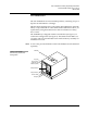
ATL P1000 Series Library Unpacking Instructions Document 6221100-02, Ver. 2, Rel. 0 March 1999 Figure 4 shows the floor space requirements for the rack-mount P1000. Figure 4 Floor Space Requirements, Rack-mount Library 24 in. (61 cm) each side 24 in. (61 cm) Front 17.5 in. (45 cm) Back 19-inch rack Library (extended from rack) 24 in. (61 cm) 30 in. (76.2 cm) Floor Clearance Floor Strength and Inclination 4 4 The stand-alone P1000 has a floor clearance of 0.75 in. (1.9 cm).
ATL P1000 Series Library Unpacking Instructions Document 6221100-02, Ver. 2, Rel. 0 March 1999 Power Inlet 4 The power inlet is an IEC-320 connector (see figure 5). For international applications, replace the power cord with a harmonized 3 x 1.0 mm2 power cord approved by the country where used.
ATL P1000 Series Library Unpacking Instructions Document 6221100-02, Ver. 2, Rel.
ATL P1000 Series Library Unpacking Instructions Document 6221100-02, Ver. 2, Rel. 0 March 1999 Unloading Space Requirements 5 Before uncrating the library, verify that you have sufficient space. For the stand-alone unit, allow a minimum of six feet in front of the ramp side of the pallet (see figure 6). Note: Unpack the library as close to the installation site as possible. Figure 6 Unloading Space Requirements, Standalone Library Library Pallet Pallet ramp Unloading area (minimum) 33 in.
ATL P1000 Series Library Unpacking Instructions Document 6221100-02, Ver. 2, Rel. 0 March 1999 Uncrating the Library To uncrate the P1000 library: Procedure 1 Open the top of the shipping carton by carefully cutting the packaging tape. The following items are stacked on top of the P1000: 10 ‡ accessories tray ‡ ramp (stand-alone library) or slide assembly (rack-mount library) 2 Remove these items from the carton and set them aside.
ATL P1000 Series Library Unpacking Instructions Document 6221100-02, Ver. 2, Rel.
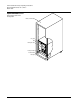
ATL P1000 Series Library Unpacking Instructions Document 6221100-02, Ver. 2, Rel. 0 March 1999 Accessories tray Figure 8 Uncrating the Rack-mount Library Slide assembly Foam supports Library Clips Procedure (continued) 4 Release the four clips that secure the carton to the pallet. To release a clip, pinch the center tabs of the clip firmly together and pull on the tabs. 5 Lift the carton off of the pallet and set it aside.
ATL P1000 Series Library Unpacking Instructions Document 6221100-02, Ver. 2, Rel. 0 March 1999 Installing the Slide Assembly in the Rack 8 If you are installing a rack-mount library, install the slide assembly in the rack before proceeding to “Removing the Library from the Pallet” on page 22.
ATL P1000 Series Library Unpacking Instructions Document 6221100-02, Ver. 2, Rel. 0 March 1999 Grounding 8 The P1000 must be connected to a grounded power outlet. If the library is rack-mounted, the rack must also be grounded. Temperature 8 The rack temperature should be less than 90qF (32qC). Determining the Mounting Position 8 To determine the mounting position of the slide assembly within the rack: Procedure 1 Locate the desired mounting position for the library (see figure 9).
ATL P1000 Series Library Unpacking Instructions Document 6221100-02, Ver. 2, Rel. 0 March 1999 Procedure (continued) 2 3 If the rack retma rail holes are not threaded, attach the appropriate threaded clips to the holes that correspond to: ‡ the mounting bracket tabs (front and back) ‡ the locking bracket tabs (front only) ‡ the temporary support screws (front and back) Insert a temporary support screw into each retma rail, just below the desired position of the slide assembly bracket.
ATL P1000 Series Library Unpacking Instructions Document 6221100-02, Ver. 2, Rel. 0 March 1999 Procedure (continued) 7 Remove the two 10-32 x 3/4 in. temporary support screws from the front retma rails and install them in the left and right rear mounting brackets to secure the rear mounting brackets to the rack retma rails. 8 Remove the two 10-32 x 3/4 in. temporary support screws from the rear retma rails and use them to finish securing the rear mounting brackets to the rack retma rails.
ATL P1000 Series Library Unpacking Instructions Document 6221100-02, Ver. 2, Rel. 0 March 1999 Adjusting the Slide Assembly Now that the slide assembly is installed in the rack, verify that: 10 ‡ The front door of the rack opens and closes freely. ‡ The rear door of the rack opens and closes freely. ‡ When fully extended, the slide assembly extends at least 30 in. (76.2 cm) from the front of the rack.
ATL P1000 Series Library Unpacking Instructions Document 6221100-02, Ver. 2, Rel. 0 March 1999 Procedure (continued) 3 When the slide assembly is in the desired position, tighten all outer nuts: a Pull the slide assembly tray forward until you can access the four rear screws. b Tighten each of the four rear nuts by holding the nut with an 11/32 inch open-ended wrench and then tightening its corresponding screw with a Phillips screwdriver.
ATL P1000 Series Library Unpacking Instructions Document 6221100-02, Ver. 2, Rel. 0 March 1999 Figure 12 Slide Assembly Tray, Fully Extended Intermediate channel lock Access hole Intermediate channel Inner channel lock Inner channel Adjusting the Slide Assembly Tray on the Slide Rails 12 To adjust the slide assembly tray on the slide rails: Procedure 1 Loosen the inner nuts on both sides of the slide assembly (see figure 13). Access these nuts from underneath the slide assembly tray.
ATL P1000 Series Library Unpacking Instructions Document 6221100-02, Ver. 2, Rel. 0 March 1999 Inner nuts Figure 13 Loosening the Inner Nuts Inner nuts Procedure (continued) 3 When the slide assembly tray is in the desired position, tighten all inner nuts: a Extend the slide assembly out of the rack until both the intermediate and inner channels of the slide rails lock (see figure 12). This allows you to access the front screws.
ATL P1000 Series Library Unpacking Instructions Document 6221100-02, Ver. 2, Rel. 0 March 1999 Procedure (continued) 4 e Use a Phillips screwdriver to tighten the screw while holding its corresponding nut with an 11/32 inch open-ended wrench. f Repeat steps 3d and 3e to tighten the remaining inner nuts. g Push the slide assembly tray back into the rack. Check for adequate clearance. If necessary, repeat this procedure to adjust the slide tray further.
ATL P1000 Series Library Unpacking Instructions Document 6221100-02, Ver. 2, Rel. 0 March 1999 Removing the Library from the Pallet This section provides separate procedures for the stand-alone and rack-mount libraries: ‡ To remove a stand-alone library from the pallet, see the following section, “Removing a Stand-alone Library from the Pallet.” ‡ To remove a rack-mount library from the pallet, see “Removing a Rack-mount Library from the Pallet” on page 24.
ATL P1000 Series Library Unpacking Instructions Document 6221100-02, Ver. 2, Rel. 0 March 1999 Figure 14 Removing the Foam Supports, Stand-alone Library Foam supports Procedure (continued) 3 Attach the ramp to the pallet using fastener strips (see figure 15). 4 Make any necessary preparations for moving the library. This may involve clearing a path to the installation site, unlocking doors, and placing mats over carpeted areas. 5 Carefully roll the library down the ramp.
ATL P1000 Series Library Unpacking Instructions Document 6221100-02, Ver. 2, Rel. 0 March 1999 Procedure (continued) 7 Roll the library to the installation site. 8 Save the shipping carton, bag, foam supports, ramp, and pallet for future use. These items are required to package the library for reshipment.
ATL P1000 Series Library Unpacking Instructions Document 6221100-02, Ver. 2, Rel. 0 March 1999 Procedure (continued) 3 With the help of a second person, lift the library from the pallet (see figure 16).
ATL P1000 Series Library Unpacking Instructions Document 6221100-02, Ver. 2, Rel. 0 March 1999 Procedure (continued) 4 Place the library on the fully extended slide assembly tray (see figure 17). Figure 17 Placing the Library on the Slide Assembly Tray Inner channel lock Screws 26 5 Secure the library to the slide tray, using six screws from the accessories kit (see figure 17).
ATL P1000 Series Library Unpacking Instructions Document 6221100-02, Ver. 2, Rel. 0 March 1999 Procedure (continued) 8 To prevent the library from sliding out of the rack during operation, secure the locking brackets to the retma rails (see figure 18). Figure 18 Locking the Slide Tray in the Rack Retma rail Locking bracket 9 Save the shipping carton, bag, foam supports, and pallet for future use. These items are required to package the library for reshipment.
ATL P1000 Series Library Unpacking Instructions Document 6221100-02, Ver. 2, Rel. 0 March 1999 Removing the Internal Packing Materials This section explains how to remove the internal packing materials that protect the library during shipping and installation. Opening the Doors 18 Caution: Before removing the internal packing materials, verify that the library is at its final installation site. Moving the library without these materials in place may damage the library.
ATL P1000 Series Library Unpacking Instructions Document 6221100-02, Ver. 2, Rel. 0 March 1999 Figure 19 Removing the Load and Bulk Packs Handles Removing the Shipping Restraint To remove the shipping restraint: 19 Note: The shipping restraint that protects the extension axis assembly is attached to the bottom drive shelf and fits over the supports for the load and bulk packs.
ATL P1000 Series Library Unpacking Instructions Document 6221100-02, Ver. 2, Rel.
ATL P1000 Series Library Unpacking Instructions Document 6221100-02, Ver. 2, Rel. 0 March 1999 Packaging the Library for Reshipment 20 If it becomes necessary to reship the library, repackage the library in its original shipping materials as follows: Procedure 1 Unload and eject all tape cartridges from the tape drives. 2 Turn off the library and disconnect all cables. 3 Open the library doors: 4 a Using the key in the accessories kit, unlock the front door of the library.
ATL P1000 Series Library Unpacking Instructions Document 6221100-02, Ver. 2, Rel. 0 March 1999 Procedure (continued) c Carefully lower the extension axis assembly so that it rests on the foam block. d Hook the lip of the shipping restraint under the edge of the bottom drive shelf (see figure 20 on page 30). e Move the gripper forward or backward as necessary so that it fits underneath the shipping restraint.