User’s Guide Quantum NDX Server BMC/IPMI 6‐67770‐01 Rev A
Quantum User’s Guide, Quantum NDX Server BMC/IPMI User’s Guide 6-67770-01 Rev A, November-2012, Product of USA. Quantum Corporation provides this publication “as is” without warranty of any kind, either express or implied, including but not limited to the implied warranties of merchantability or fitness for a particular purpose. Quantum Corporation may revise this publication from time to time without notice. COPYRIGHT STATEMENT Copyright 2012 by Quantum Corporation. All rights reserved.
Preface About this User's Guide This user guide is written for system integrators, PC technicians and knowledgeable PC users who intend to configure the IPMI settings supported by the Nuvoton WPCM450 BMC Controller embedded in the motherboard in Quantum's NDX servers. It provides detailed information on how to configure the IPMI settings supported by the Nuvoton WPCM450 chip. Note: Nuvoton Technology is a subsidiary of Winbond Corp.
Toll Free: 1-800-284-5101 United States Toll: +1-720-249-5700 Europe, the Middle East, and Toll Free: +800-7826-8888 Africa (EMEA) Toll: +49-6131-3241-1164 Asia and Pacific (APAC) Toll Free: +800-7826-8887 Toll: +603-7953-3010 For worldwide support: http://www.quantum.com/ServiceandSupport/index.
Table of Contents Chapter 1: 1.1 An 1.1.1 1.1.2 1.1.3 Introduction ...................................................................................... 1 Overview of the WPCM 450 BMC Controller ............................................................ 1 WPCM450 DDR2 Memory Interface ........................................................................... 1 WPCM450 PCI System Interface ................................................................................
YAFUFlash ................................................................................................................................ 46 YAFUKCS ................................................................................................................................. 46 2. Flashing the BMC Firmware in the DOS Environment ................................................... 46 Examples ............................................................................................................
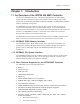
Chapter 1: Introduction Chapter 1: Introduction 1.1 An Overview of the WPCM 450 BMC Controller The Nuvoton WPCM450 Controller, a Baseboard Management Controller (BMC), supports 2D/VGA‐compatible Graphic Cores with PCI interface, creating multi‐media virtualization via Keyboard/Video/Mouse Redirection (KVMR). The WPCM450 Controller is ideal for networking management. The WPCM450 Controller interfaces with the host system via PCI connections to communicate with Graphic cores.
Chapter 1: Introduction Voltage monitoring Power status monitoring, chassis intrusion monitoring Remote power control to power‐on, power‐off or reboot a system Remote access to text‐based, graphic‐based system information, including BIOS configurations and OS operation information (KVM)Remote management of utility/software applications Provides Network Management Security via remote access/console redirection.
Chapter 2: Configuring the IPMI Settings 1.4 Motherboards Supported This version of Embedded BMC/IPMI is supported by the motherboards listed in the table below. Intel X9SCL-F 1.5 An Important Note to the User The graphics shown in this user's guide were based on the latest information available at the time of publishing of this guide. The IPMI screens shown on your computer may or may not look exactly like the screen shown in this user's guide.
Chapter 2: Configuring the IPMI Settings Chapter 2: Configuring the IPMI Settings With the Nuvoton WPCM450 BMC Controller and the IPMI firmware built in, the motherboard(s) allow the user to access, monitor, manage and interface with multiple systems in various remote locations. The necessary firmware for accessing and configuring the IPMI settings are available on Quantum's website at http://www.quantum.com/ServiceandSupport/SoftwareandDocumentationDownloads/N DX8/Index.
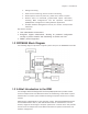
Chapter 2: Configuring the IPMI Settings 2.1.1 Using IE* to Access the BMC/IPMI Settings from Your Computer You can access BMC/IPMA settings through Microsoft Internet Explorer. This section describes how. 2.1.1.1 To Log In Once you are connected to the remote server, the following screen will display. 1. Enter your Username. 2. Enter your Password and click . 3. The Home Page will display on the next page. Note 2: The manufacturer default username and password are ADMIN.
Chapter 2: Configuring the IPMI Settings 2.1.1.2 IPMI Main Page Once you are logged into the IPMI utility, the IPMI Main page will display. The IPMI screen contains the following three sections: 1. The Submenu Bar (Top) 2. The Options Window (Left) 3. The Main Display area (Center) The submenu bar on the top lists the following submenus: Submenu Bar System This submenu displays system information. Information Server Health This submenu displays server health monitoring status.
Chapter 2: Configuring the IPMI Settings 2. The Options window The Options window on the left side allows the user to quickly navigate through different submenu options. Options window Submenu Name (System Information) Click this item to display and configure a submenu items. Refresh Page Click this icon to refresh the page. Logout Click this icon to logout from the IPMI utility. 3. The Main Display Area This area displays the items included in a submenu.
Chapter 2: Configuring the IPMI Settings 2.1.2 Server Health This feature allows the user to set Server Health Settings. Click to display the following submenu. The Server Health submenu contains the following items. o Sensor Readings o Sensor Readings with Thresholds o Event Log 2.1.2.1 Sensor Readings Click this item to display the Sensor Reading page as shown below.
Chapter 2: Configuring the IPMI Settings monitoring. o OEM Reserved: This item reserved for OEM use. 2.1.2.2 Sensor Readings with Thresholds Click this item to display all sensor readings and their thresholds as shown below. 1. From the pull‐down menu select a sensor you want to display its readings and thresholds. 2. Name: This item displays the name of the item being monitored. 3. Status: This item displays the status of the sensor item. 4.
Chapter 2: Configuring the IPMI Settings Any item with a reading below this threshold is not in a critical state.
Chapter 2: Configuring the IPMI Settings 9. High CT (High Critical‐Threshold): This is the high threshold of a critical item. Any item with a reading above this threshold is in a critical state. 10. High NR (High Non‐Recoverable): This is the high threshold of a non‐recover‐ able item. Any item with a reading above this point will not be recovered. 11. Refresh: Click this tab to refresh this page. 12.
Chapter 2: Configuring the IPMI Settings 2.1.2.3 . Event Log This feature allows the user to configure Event Log settings. When you select Event Log in Options Window the following page will display. 1. From the pull‐down menu select an event category to show the vent log, which includes the following categories: All Events, Sensor‐Specific Events, BIOS‐Generated Events, and System‐Management Software Events.
Chapter 2: Configuring the IPMI Settings 2. Event ID: This item displays the event ID of this event. 3. Time Stamp: This item displays the time when the event takes place. 4. Sensor Name: This item indicates the name of the sensor (device) to which the event has occurred. 5. Sensor Type: This item indicates the type of the event. 6. Description: This item provides a brief description of the event. 7. Event Log: This item indicates the number of events included on the event log. 8.
Chapter 2: Configuring the IPMI Settings 2.1.3 Configuration This feature allows the user to configure various network settings. Click the Con‐ figuration on the submenu bar to display the Configuration submenu as shown below. Select an item to configure its settings. The items included are listed below. o Alerts: This item allows the user to configure Alerts settings. o Date & Time: This item allows the user to configure Date & Time settings.
Chapter 2: Configuring the IPMI Settings 2.1.3.1 Configuration ‐ Alerts This feature allows the user to configure Alert settings. When you click in the Options window, the following screen will display. 1. Alerts: Click this item to add, to modify, to delete or to define the setting of an. 2. Alert#: This item lists Alert item numbers. 3. Alert Level: This item indicates the alert level for each alert. 4.
Chapter 2: Configuring the IPMI Settings 2.1.3.1.1 Modifying Alerts When you select an item and click , the Modify Alert submenu will display as shown below. To modify an alert, enter the information needed for the following items: o Alert Type: This item allows you to specify the alert type. You can select SNMP Type or Email from the pop-up menu. For further guidance on typical inquiries relating to SNMP, see the table below. Item SNMP version number Answer SNMP version 2.
Chapter 2: Configuring the IPMI Settings Note: To set up an email alert, please enter the IP address of your mail server in the SMTP (Simple Mail Transfer Protocol.) 2.1.3.2 Configuration ‐ Time and Date Settings This feature allows the user to configure time and date settings for the host server and client computer. When you click in the Options window, the following screen will display. 1. Time and Date: Click this item to configure the settings. 2.
Chapter 2: Configuring the IPMI Settings 2.1.3.3 Configuration ‐ Light‐Weight Directory Access Protocol (LDAP) Settings This feature allows the user to configure Light‐Weight Directory Access Protocol (LDPA) settings. When you click in the Options window (1), the following screen will display. Examples and Explanations of the LDAP settings are shown below: 1. Port: 389‐This item indicates the port number of the LDAP server. 2. IP Address: xx.xx.xx.
Chapter 2: Configuring the IPMI Settings 2.1.3.4 Configuration ‐ Active Directory Settings This feature allows the user to configure Active Directory settings. When you click in the Options window, the following screen will display. 1. Active Directory: Click this item to configure Active Directory settings. 2. If Active Directory is currently disabled, click to enable it. 3.
Chapter 2: Configuring the IPMI Settings 2.1.3.5 .a Configuration ‐ Active Directory ‐ Advanced Settings This feature allows the user to configure Active Directory‐Advanced settings. When you click in the Options window and checked the Enable box indicated on the previous page, the following screen will display. 1. Active Directory: Click this item and check the Enable box on the previous page to configure Active Directory settings. 2.
Chapter 2: Configuring the IPMI Settings 2.1.3.6 Configuration ‐ Mouse Mode This feature allows the user to configure mouse mode settings. When you click in the Options window, the following screen will display. 1. Mouse Mode: Click this item to configure the mouse mode settings. 2. Set Mode to Absolute: Check this radio button to use the Absolute mode for the Windows OS. (This is the default setting.) 3.
Chapter 2: Configuring the IPMI Settings 2.1.3.7 Configuration ‐ Network Settings This feature allows you to configure network settings. When you click in the Options window, the following screen will display. 1. Network: This item allows you to view or modify network settings. 2. MAC Address: Enter the MAC address for your network. Check the first radio button to obtain an IP address automatically by using DHCP (Dynamic Host Configuration Protocol).
Chapter 2: Configuring the IPMI Settings 2.1.3.8 Configuration ‐ Remote Session This feature allows the user to configure remote session settings. When clicking in the Options window, the following screen displays. 1. Virtual Media Attach Mode: Click the pull‐down menu to display virtual media attach modes. Attach: Select this mode to activate a virtual media to make it available for remote access.
Chapter 2: Configuring the IPMI Settings 2.1.3.9 Configuration ‐ SMTP Settings This feature allows the user to configure SMTP (Simple Mail Transfer Protocol) settings for email transmission through the network. When you click in the Options window, the following screen will display. 1. SMTP: Check this item to configure SMTP (Simple Mail Transfer Protocol) settings for email transmission across the IP network. 2.
Chapter 2: Configuring the IPMI Settings 2.1.3.10 Configuration ‐ SSL Upload Settings This feature allows the user to configure upload settings for encrypted data to transmit across the internet by using the Secure Sockets Layer (SSL) protocol. When you click in the Options window, the following screen will display. 1. SSL: Check this item to configure SSL Upload settings for the encrypted data to securely transmit through the internet. 2.
Chapter 2: Configuring the IPMI Settings 2.1.3.11 Configuration ‐ Users Settings This feature allows you to change user settings. When you click in the Options window, the following screen will display. 1. Users: Select this item to configure the user settings. The current users list is displayed. 2. User ID: This item displays the ID of a user. 3. User Name: Use this item to enter and display a user name. 4.
Chapter 2: Configuring the IPMI Settings 2.1.3.12 Configuration ‐ LAN Select This feature allows you to select LAN ports. When you click in the Options window, the following screen will display. 1. LAN Select: This item allows the user to select the LAN port for IPMI communication. 2. Enable: Click to enable LAN Port Select support. Dedicated LAN: Select this item to direct all IPMI communication to the IPMI Dedicated LAN port.
Chapter 2: Configuring the IPMI Settings 2.1.3.13 Configuration ‐ Ports This feature allows you to change LAN Port settings. When you click in the Options window, the following screen will display. Ports Setting: This item allows you to modify the following LAN port settings. 1. 2. 3. 4. Web Port: Default is 80 Web SSL Port: Default is 443 IKVM Port: Default is 5900 Virtual Media Port: Default is 623 Click to save port settings.
Chapter 2: Configuring the IPMI Settings 2.1.4 Remote Control - the Main Menu This section allows the user to carry out activities and perform operations on a remote server via remote access. This submenu allows you to configure the remote control settings. Remote Control: Click this item to configure Remote Control settings. 1. Launch Console: Click this button to launch Remote Console via Java or IE. 2.
Chapter 2: Configuring the IPMI Settings 2.1.4.1 Remote Console This feature allows you to perform various activities on the server. When you click in the Options window, the following Remote Control submenu screen will display. Follow the instructions below to launch the remote console. 1. Remote Control: Check this item to enable remote console support and manage the server from a remote site via Java or Active X (for Internet Explorer). 2.
Chapter 2: Configuring the IPMI Settings Quantum NDX Server BMC/IPMI User’s Guide Page 31
Chapter 2: Configuring the IPMI Settings Page 32 Quantum NDX Server BMC/IPMI User’s Guide
Chapter 2: Configuring the IPMI Settings 2.1.4.1.1 Remote Console ‐ Video This feature allows you to configure video settings for your remote console. When you click
Chapter 2: Configuring the IPMI Settings 1. Keyboard: Click this item to configure and manage the keyboard settings of a remote server via the Remote Console. 2. Options: The pull‐down submenu contains the options listed below. o Hold Right Alt Key: Check this item to emulate the right alt key when it is pressed. o Hold Left Alt Key: Check this item to emulate the left alt key when it is pressed.
Chapter 2: Configuring the IPMI Settings 5. Keyboard pass‐through: Click this item (1) to use your local keyboard for the remote console. Note: Keyboard Pass-through provides full keyboard support. It sends all keys, including special key combinations to the host server. 6. Modifier Key: Click a button to select the soft keyboard mode. Combination: Click the button to use a special key combination as a single key.
Chapter 2: Configuring the IPMI Settings Page 36 Quantum NDX Server BMC/IPMI User’s Guide
Chapter 2: Configuring the IPMI Settings 2.1.4.2 Remote Control‐Launch SOL This feature allows you to launch the remote console by using Serial_over_LAN. Follow the instructions below to launch SOL. 1. Launch SOL: Click this item to access a host server via Console Redirection. It also allows a system administrator to monitor and manage a server from a remote site. 2.1.4.2.1 Launching SOL 1.
Chapter 2: Configuring the IPMI Settings 4. Click to invoke the submenu, which will allow you to select the Baud Rate for serial line transfer. 5. Baud Rate (bps): You can select a Baud rate from the list as your SOL transfer rate. The options are: 9600 bps (bit‐per‐second), 19200 bps, 38400 bps, 57600 bps, 115200 bps, and default. Make sure that the Baud Rate selected here matches the Baud Rate set in the BIOS.
Chapter 2: Configuring the IPMI Settings 2.1.4.3 Server Power Control This feature allows you to configure power management settings for your remote console. To configure Server Power Control settings, follow the instructions be‐ low. 1. Click in the Menu bar to invoke the Remote Control Main Page. 2. Click to display the Power Control submenu as shown above. 3.
Chapter 2: Configuring the IPMI Settings 2.1.5 Maintenance Use this feature to manage and configure IPMI devices. Follow the instructions below to configure Maintenance settings. 1. Click in the Menu bar to display the Maintenance page. 2. Click to update the BMC firmware (the BIOS) of the remote server. The Firmware Update screen is shown in the next section. 3. You can also press to reboot the BMC (IPMI) Controller.
Chapter 2: Configuring the IPMI Settings 2.1.5.1 Maintenance ‐ Firmware Update When you click in the Menu bar, the Maintenance Main page will display as below. Enter Update Mode: Click this item to enter the update mode. Warning: Once you've entered the firmware update mode, the device will be reset even if you cancel the process of firmware updating. Notes: 1. When updating firmware, you are given the option to "Preserve Configuration.
Chapter 2: Configuring the IPMI Settings Browse: Click Browse to select the location of the Floppy ISO image. 2. Connect Floppy: After selecting the Virtual Media for your Remote Console, click to connect to the remote console via the Floppy drive you chose. 3. CD Media: This item allows the user to configure CD Media settings. The sub‐items include the following.
Chapter 2: Configuring the IPMI Settings 2.1.6 Miscellaneous This feature allows the user to perform network activities. Click in the Menu bar to display the Miscellaneous page. 1. Post Snooping: Click this item to query the POST (Power_On_Selt‐Test) Snooping code for BIOS LPC Port80. 2. UID: Click this item to enable or disable UID (unit identification) support as shown on the next page.
Chapter 2: Configuring the IPMI Settings 2.1.6.1 Miscellaneous ‐ UID (Unit Identification) This feature allows the user to enable or disable UID support. Click in the Menu bar to display the Miscellaneous page. 1. This item shows the current UID status. 2. This item allows the user to enable or disable UID support for console redirections. After clicking the enable UID button or disable UID button, click to it to take effect.
Chapter 3: Frequently Asked Questions Chapter 3: Frequently Asked Questions Question: How do I flash the IPMI firmware? Answer: 1. Log in the IPMIcfg utility by entering the system IP address. 2. Click the button. Browse the files to select a correct file to flash the firmware. 3. Click the button to proceed with firmware flashing. Question: How do I set up the IP address and MAC address for remote access? Answer: 1. Boot the system into DOS.
Appendix A: Appendix A: Flash Tools 1. Overview This chapter provides instructions on how to use AMI Flash Tools. The Flash Tools allow the user to use Command_Line (CL) utility programs to upgrade or update firmware via different channels such as KCS, USB and LAN connections. We are going to focus on the following tools in this manual. 1. YAFUFlash 2.
Appendix A: Examples Example 1 /Yafukcs ‐info rom.ima Description: This command displays the details of both existing and new firm‐ ware. Example 2 /Yafukcs ‐full rom.ima Description: This command starts flashing the new rom.ima to the firmware. Example 3 /Yafukcs ‐full ‐force‐boot rom.ima Description: This command starts flashing the new rom.ima to the firmware using "FORCE BootLoader upgrade." 3.
Appendix A: Format: Yafuflash [OPTION] [MEDIUM] [FW_IMAGE_FILE] [OPTIONS] Options Commands ‐info This option displays information regarding existing and new ‐auto This option allows for automatic upgrades by comparing flash ‐full This options allows for full upgrades. ‐force‐boot Select this option to force the boot loader to be upgraded during full upgrade. The boot loader is "preserved" by default. ‐c This option preserves configuration modules during full upgrade.
Appendix A: Example 3 Yafuflash ‐nw ‐ip 155.166.132.12 ‐full ‐force‐boot rom.ima Description: This command starts flashing the new rom.ima to the firmware with FORCE BootLoader Upgrade via the network connection using the IP address of 155.166.132.12. Using USB as a Medium Example 1 Yafuflash ‐cd ‐info rom.ima Description: This command displays the details of both existing and new firmware using a USB connection. Example 2 Yafuflash ‐cd ‐full rom.
Appendix A: 4. Flashing the BMC Firmware in the Linux Environment YAFUFlash is used to flash the BMC firmware in the Linux environment using network or USB connections. To flash the BMC in Linux, follow the instructions below. 1. Open the Terminal. Go to YafuFlash/Linux path. 2. The file libipmi.so 1 should be accessible to a Linux system. Usually when running an application, Linux will search for a file in dependent libraries in default locations, such as usr/lib/lib folders. 3. Copy libipmi.
Appendix A: [FW_IMAGE_FILE] The firmware‐image file name is [rom.ima]. Using Network as a Medium Example 1 /Yafuflash ‐nw ‐ip 155.166.132.12 ‐info rom.ima Description: This command displays the details of both existing and new firmware using the network connection with the IP address of 155.166.132.12. Example 2 /Yafuflash ‐nw ‐ip 155.166.132.12 ‐full rom.ima Description: This command starts flashing the new rom.ima to the firmware using the network connection with the IP address of 155.
Appendix A: 5. Firmware Recovery If the firmware upgrade is interrupted during firmware flashing, please follow the steps listed below for firmware recovery using Yafukcs. 1. Power off the system by disconnect the power cord. 2.
Page 53 Quantum NDX Server BMC/IPMI User’s Guide