FastStor® 1 Installation and User Guide Advanced Digital Information Corporation
Copyright © 2005 ADIC The information contained in this document is subject to change without notice. This document contains proprietary information which is protected by copyright. All rights are reserved. No part of this document may be reproduced, modified, distributed, or translated to another language without prior written consent of ADIC. ADIC USA 11431 Willows Road NE Redmond, Washington 98052-4952 Tel.
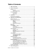
Table of Contents 1 About This Guide ................................................................................1 2 General Information............................................................................3 Models ..................................................................................................4 Capacity .....................................................................................4 Data Transfer Rates...................................................................
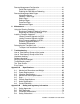
Remote Management Configuration ................................................... 41 Quick Start Instructions ............................................................ 41 Enabling the RMI Without Rebooting ....................................... 41 Remote Management Web Pages...................................................... 42 Information Boxes .................................................................... 42 FastStor 1 Start Page..............................................................
List of Figures and Tables Figure 2.1 Overview of ADIC FastStor 1 ............................................................3 Table 2-1 Data Storage Capacity ...............................................................4 Table 2-2 Data Transfer Rates...................................................................4 Figure 2.2 Front panel of the FastStor 1.............................................................5 Figure 2.5 Rear panel of the FastStor 1 ..............................................
Figure 7.1 Error Code Page ............................................................................. 61 Figure 7.2 Example of detailed information ...................................................... 61 Figure 7.3 Example of further detailed information........................................... 61 Figure 7.4 Example of action............................................................................ 62 Figure 7.5 Warning message concerning reboot..............................................
1 About This Guide This guide describes how to install and use the ADIC FastStor 1 with an LTO tape drive. It is intended for use by anyone who installs, uses and maintains the device. Chapter 2: General Information provides a product description of the FastStor 1. Chapter 3: Installation describes how to install the device. Chapter 4: Operating and Configuration describes how to use the local interface, how to configure the device, and how to handle the cartridges and magazines.
2 FastStor 1 Installation and User Guide
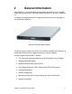
2 General Information ADIC FastStor 1 is a compact tape cartridge loader designed for secure, reliable, unattended system backup. The loader can be mounted in a 19” rack. Its height is 1U. The loader is equipped with oneLTO tape drive and has room for 8 cartridges in two 4-cartridge magazines. Figure 2.1 Overview of ADIC FastStor 1 The entire system is under host control via an industry-standard SCSI interface. Its robotic tape handling is both rugged and simple for utmost reliability.
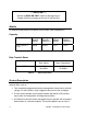
*** IMPORTANT *** Review the READ ME FIRST caution at the beginning of Chapter 3 before you power up the unit for the first time. Models For additional specification information for this model, refer to Appendix A. Capacity FastStor 1 Model Cartridge Capacity (Native) Cartridge Capacity (Comp 2:1) Magazine Capacity (Native) Magazine Capacity (Comp 2:1) ADIC FastStor 1 LTO2 200GB 400GB 1.6TB 3.
the operations that can be done through the front panel, such as monitoring the loader’s status and downloading statistical and diagnostic information. For information on the installed tape drive, see the tape drive manuals referred to in Chapter 1. Front Panel The Front Panel includes the User Control Panel with LCD display, four Control Buttons, two LED indicators and a Standby switch. The bezels of the two magazines are also visible from the front.
LED Indicators The two LED indicators are green and amber. They indicate the FastStor 1 activity as follows: • Green LED on: The FastStor 1 is either running or ready for operation. • Green LED blinking: Short blinks followed by long intervals indicate that the loader is in low power standby mode. • Amber LED on: Fault LED; the FastStor 1 has encountered an electrical or mechanical failure. • Both LED’s off: The FastStor 1 is offline.
Main Power Switch/ Fuse/Power cord connection The main power switch is found on the rear of the loader on the power supply bracket. The power switch, the fuse holder (with a 250V 2A (H) fuse) and the AC power cord connection are combined in one common unit. SCSI Interface Connectors The FastStor 1 has two shielded 68-pin VHDCI SCSI connectors on the rear panel. The connectors are used for connecting the tape drive and the FastStor 1 to a SCSI bus.
8 FastStor 1 Installation and User Guide
3 Installation This chapter provides step-by-step instructions on how to properly prepare and install the ADIC FastStor 1. READ ME FIRST CAUTION! ! YOU MUST REMOVE THE ROBOT TRANSPORT LOCK WHEN POWERING UP THE UNIT FOR THE FIRST TIME OR IT WILL NOT OPERATE. SEE THE PROCEDURE ON THE FOLLOWING PAGES. Performing the Installation To install the FastStor 1, complete the following steps. Step 1. Unpacking the FastStor 1 Carefully unpack the unit from the shipping container.
cartridge labels) There may be variations of this list. Note: The FastStor 1 contains no cartridges before shipment. Step 2. Installing the FastStor 1 in a Rack The FastStor 1 is designed for use in a 19” rack system using 1U of rack space. The length of the power cord and the SCSI cable may restrict the placement. Attention: The FastStor 1 is designed to operate in a horizontal position. Do not attempt to operate the FastStor 1 in any other position than horizontally.
Back Rail Right Assembly Rail Left Assembly Front Figure 3.1 Rack Mounting kit Installing the Rack Mounting Kit • Determine the proper position of the rails in the rack. Caution: Consider rack stability when deciding where to place the FastStor 1. Hazardous conditions can result from uneven mechanical loading of a rack. The FastStor 1 uses 1U of vertical rack space. The rails must be installed in a full U position (The bottom of the rails must be aligned with the bottom of a U). See figure 3.2.
Figure 3.2 Rack mount rail Installing the “Rail Left Assembly” 1. Measure the length between the rear rack mount rails and the front rack mount rails. If the measurement is shorter than the FastStor 1, move the two sets of screws M4x12, washers and nuts shown in Figure 3.3. 2. Adjust the “Rail Left Assembly” to fit the measurement in step 1. 3. Use a 7 mm open-end wrench together with the screwdriver to tighten the two M4x12 screws to fix the rail length.
Installing the “Rail Right Assembly” On the right side of the rack, follow the “Rail Left Assembly” instructions, substituting “right” where “left” is referenced. Use these holes if rack depth is equal or longer than the FastStor 1 Rear Rack Mount Rail Step 5 (Screw M6x12) Step 1 Holes to be used if rack depth is shorter than the FastStor 1 Step 1 Step 3 (Screw M4x12, nut and washer) Front Rack Mount Rail Step 2 Step 5 (Screw M6x12) Figure 3.3 Mounting the Rack mounting kit to a rack Figure 3.
Mounting the FastStor 1 to the Rack Make sure all the screws in the Rack Mounting Kit are tightened properly before installing the FastStor 1 in the rack. Slide the FastStor 1 on the rails from the front of the rack, as shown in figure 3.5. Then fix the FastStor 1 using one M6x12 screw in front of the rack on both left and right side (see figure 3.6) and one M5x8 on the backside of the Rack Mounting Kit on both left and right side (see figure 3.7). Figure 3.
Slide the FastStor 1 gently out of the rack. Note that the FastStor 1’s weight is 32 pounds. Step 3. Connecting Power Cable Before connecting the FastStor 1 to your host computer system, you should run the unit’s self-diagnostic test. This preparation requires power to the FastStor 1. Follow these steps to perform this test: 1. Use the power cables from the accessories included in the shipment. Make sure you select the power cord suited for your power system. 2.
Step 4. Removing the Transport Lock Figure 3.9 Magazine lock marked with red plastic tab The robot mechanism is protected from damage during shipment with a screw holding the robotics in a locked position. This locking screw is marked with a red plastic tab protruding between the right magazine and the front panel assembly. This locking screw must be removed before the FastStor 1 can operate normally. The locking screw will be detected when the FastStor 1 is powered on.
procedures for resolving the problem. Step 6. Setting the SCSI Address The SCSI address is a unique address that identifies the unit connected to the SCSI bus. The FastStor 1 uses two SCSI addresses or ID’s. One is for the loader robotics controller, and the other is for the tape drive. The SCSI addresses can be configured through the operator buttons and the display on the front panel. In most cases the default addresses can be used.
2. Secure the cable with the thumbscrews on the connector. 3. Connect the other end of the SCSI cable to the appropriate SCSI adapter on your system, and fasten it with the thumbscrews. 4. If the FastStor 1 is the last device on the SCSI bus, install a SCSI bus terminator to the free SCSI connector on the FastStor 1. Make sure the terminator is of the correct type for your SCSI system. 5. It is possible to daisy chain several SCSI devices on the SCSI bus.
system is started. Step 10. BCR: Labeling cartridges Your loader is equipped with a barcode reader. If you want to use this functionality, you must attach barcode labels to the cartridges. Note: You must use FastStor 1-specific barcode labels to ensure reliable functionality of the barcode reader. Cartridge labels must be oriented on the cartridges as shown in the figure below with the locking mechanism to the left. Figure 3.11 Positioning of barcode label for LTO cartridges.
4 Operation and Configuration The Local User Interface (LUI) consists of a small LCD panel capable of displaying four lines of 20 characters each, and four control buttons, one near each corner of the display. The buttons have soft labels in the corners of the display. The figure below shows the power-on screen on the panel. Figure 4.1 Power-on Screen System Power-On With mechanical installation and electrical connection complete, turn on the AC power switch.
The map of the cartridges has the following symbols: 1. A “?” when status is unknown and Inventory is still running. 2. A number indicates a slot occupied by a cartridge. (Figure 2.3 shows how the cartridge slots are numbered in the magazines.) 3. An underscore line indicates an empty slot. 4. ”C” indicates that a Cleaning Cartridge occupies the slot. The line below the map on the default screen gives the drive status. The drive status displayed is drive dependent.
The Drive Status line (line 3) can show the following statuses: 1 Drive Empty There is no cartridge in the drive. 2 Drive Loaded A cartridge is loaded. 3 Drive Idle A cartridge is loaded and the drive is ready to use it. 4 Drive Rewinding The drive is rewinding the tape 5 Drive Seeking The drive is searching for specific data on the tape. 6 Drive Reading The drive is reading data for transfer to a host via the SCSI interface.
Front Panel Display Modes The front panel displays three types of screens for different purposes: menus, dialogs and messages. Menus The major contributor is the MENU. It is used to select operations to perform by enabling the operator to navigate a menu tree using the control buttons. Due to the size of the display, only one menu item is shown at a time. See Figure 4.4 for a standard menu layout, and Figure 4.5 for a complete menu tree. ▲ EXIT Menu Entry. ▼ SELECT Figure 4.
Figure 4.
Dialogs A dialog is a screen type used to get detailed input from the operator, such as a SCSI ID, name, or password. See Figure 4.6. ▲ Ok Main Dialog text Dialog Entry value 4 ▼ Figure 4.6 Standard Dialog Layout. The dialogs come in several forms, but there are only a few main types. Dialogs, Discrete Values The dialog in Figure 4.7 is used to enter discrete values. It handles one character or digit at a time. The digit or character being manipulated is said to be in focus.
two digits. (The maximum value allowed in this dialog is “255” within each group.) If, however, “2” is selected, only values between “0” and ”5” are available in the second digit. If a value between “0” and “4” is selected for the second digit, “0” to “9” is available for the third, but if “5” is selected for the second digit, only “0” to “5” is available for the third one.
Messages Messages can inform the operator about situations that arise during operation, such as error conditions and situations where a process requires operator approval or intervention to continue. An example of the latter is when the loader detects a wrong magazine type. The loader will eject that magazine and show the message “Left (or right) magazine is the wrong type”. This message is removed by inserting a correct type magazine.
Main Menu The Main menu contains a set of frequently used functions and links to a set of sub menus. Item name Description Load to Drive Loads a cartridge from a selected magazine slot into the drive. When Select is pressed on this menu item, a magazine slot selection dialog is displayed. The operator must scroll to the wanted slot and press Ok to start the operation. The progress of the operation is displayed, and when the loader part of the operation is completed, the main menu is displayed.
the main menu entries except the View Data entry is selected, the loader will go to its busy state, and SCSI commands will be terminated with Check Condition and Not Ready status. Setup Menu To enter this menu, scroll to the Setup item in the Main Menu and press the Select button. The loader enters the busy state when this menu is selected. Item name Description FastStor 1 setup This menu item gives access to the FastStor 1 setup menu. SCSI setup This menu item gives access to the SCSI bus setup menu.
Item name Legal values. Default value Loader SCSI ID Legal SCSI ID: 00..15 04 Drive SCSI ID Legal SCSI ID: 00..15 05 Loader Parity Enabled, Disabled Disabled Loader Personality LTO: FastStor 1 FastStor 1 Remote Management setup The Remote management setup menu allows enabling, configuration and access control to the loader via the loader’s Remote Management Web interface.
Select button. The loader will remain in its ready state when this menu is selected. The View Data menu contains the values assigned during device setup (see Setup Menu), and also statistical data related to the drive and the robotics. The view-only fields display data that can be changed from the Setup menu only. If you select the Change button and the robot is idle, a dialog appears where the value may be changed. This requires entering a password if the Loader Password system is enabled.
Drive Info The different drive types used in the FastStor 1 might not provide all the information listed below. If an unavailable entry is selected, the string “Data Unavailable” is displayed. Item name Legal values Default value Drive Product ID Drive Inquiry Product Id Drive dependent Drive Vendor ID Drive Inquiry Vendor Id Drive dependent Drive FW Revision Drive Firmware Revision Drive dependent Drive Serial No.
Stow Statistics When selected, the operator can scroll through the stow count and stow retries for the drive and all magazine slots. Power On Time Displays Power On Hours for the loader Time since clean If available from the drive, this entry displays the number of hours since the drive was last cleaned.
Drive test Starts a drive self test. (Only when supported by the installed tape drive.) Hardware test Runs a test of the loader hardware, including the Loader internal cabling. Set Password Item name Description Set Password Allows the operator to set a four-digit password protection for the menu system. The default password is <0000>, meaning the password is disabled. WARNING: If you set a password, make sure you do not forget it.
The robot removes the cartridge from the selected magazine slot and moves it to the drive. To unload a cartridge from drive: 1. From the default display, press the menu button and select Unload from Drive from the main menu. A screen similar to Figure 4.12 displays the available slots. Ok Cancel Unload from drive To Slot: 24678 3 4 Figure 4.12 Unload From Drive 2. Select the cartridge slot number of your choice. Press the 4 button to increment and the 3 button to decrement. 3. Press the Ok button.
Menu. The following screen, Figure 4.14, appears, identifying the magazine: ▲ Exit Eject both mags. ▼ Select Figure 4.14 Removing magazine Scroll to the correct magazine (Both, Left or Right magazine) and press Select. The selected magazine will pop out 2 to 3 cm, See next figure. The display will show a message telling that the magazine or magazines is/are ejected. If only one magazine is ejected, the display indicates a button to push to eject the other magazine. Figure 4.
Figure 4.16 Removing the magazine from the loader Inserting Cartridges into the Magazine When inserting cartridges, the access door of the cartridge must face the magazine. Push it carefully into the magazine until it locks in place. The rear side of the cartridge with the Write Protect switch and the barcode label must face out. Make sure the cartridges latch properly. Figure 4.
could be lost. Pull the cartridge carefully out of the magazine slot. Figure 4.18 Push the release knob towards the cartridge to eject Figure 4.19 Cartridge position after manual release from magazine slot Inserting a Magazine into the Unit The right and left magazines are mirrored and can only be inserted into the correct left or right magazine bay. See Figure 4.20. 1. Enter the back of the magazine into the correct magazine bay. Make sure it is in level with the loader. 2.
Figure 4.20 Push magazine until it clicks into place Manual/Emergency Release of Magazines In failure situations (either in the loader itself, a power loss, or situations where you need to manually release the magazines), a manual/emergency release is available. To activate the emergency magazine feature, you must use the special magazine release tool that is part of the accessory kit shipped together with the FastStor 1. This tool must be inserted through the hole marked in Figure 4.21.
Figure 4.22 shows the release tool inserted into the correct hole on the right hand side magazine bezel. Figure 4.22 Magazine release tool in use Standby Functionality On the front panel a standby button is available. To activate Standby mode, press the button for a minimum of 2 seconds. The FastStor 1 will enter a standby mode in a controlled manner. The following takes place before the FastStor 1 goes into standby mode: 1. Finish any FastStor 1 activity. 2.
5 Remote Management In order to facilitate Remote Management, the FastStor 1 is equipped with an Ethernet interface and a built in web server. The Remote Management Interface (RMI) can be accessed with a standard web browser, such as Internet Explorer, Mozilla or Opera. Remote Management Configuration In order to start the FastStor 1 Remote Management Interface, the FastStor 1 must obtain a valid IP address.
Addr. mode to DHCP mode. 3. Via the front panel, first set Setup → Remote management → Access control → Allow remote man. to “Not allowed” and select “OK.” Then set the same value to “Allowed” and select “OK.” This will restart the networking subsystem. Obtaining a new IP address may take some time if the FastStor 1 is in DHCP mode. 4. Check the IP address via the front panel by accessing either View Data → Remote man. info → Sta IP Addr. state or View Data → Remote man. info → Dyn IP Addr.
FastStor 1 Start Page After successfully connecting to the FastStor 1 from your browser, you will see the FastStor 1 Start page, Figure 5.2. This contains: • Select language for user-interface. 1. The language used last time will come up as the default language at start-up. 2. The default language is English. • Log in to use Remote Management. The system has two levels of login. By default the passwords are blank. (That is, type in the user ID and leave the password field blank.
plaintext password, but it is possible to sniff “the challenge key” and use it to gain access. The system is therefore not safer than the network it is using. If you need high security, make sure packets to and from the FastStor 1 do not leave the secure network, and employ separate encryption when traffic traverses unsecured networks. Status Page The FastStor 1 Status page looks like the figure below. Figure 5.
If you click on a slot, additional cartridge information is shown in a pop-up window. This information includes the cartridge barcode (if label and barcode reader are installed) and the error code. Settings Pages You can change the FastStor 1 configuration on the setting pages. These pages can be accessed only by someone who is logged in as Administrator. Personalization On this page you can change the Remote Management passwords.
Figure 5.4 Remote Management Command Page Maintenance Pages On these pages it is possible to select predefined tests and actions to check the FastStor 1’s reliability. In addition it is possible to upgrade the loader's firmware over TCP/IP. Diagnostics • Clean the drive by importing a cleaning cartridge. • If you choose Identify loader, the front panel display light toggles on and off for 15 seconds.
current cartridge locations. FW Upgrade Upgrade the loader's firmware by uploading a binary file. The loader must be configured to allow remote firmware upgrade. This configuration is done by using the front panel interface (Menu → Setup → Remote management → Access control → Allow rem. FW.upg.).
6 Maintenance Using the Cleaning Cartridge The cleaning cartridge is similar in size and shape to the regular LTO data cartridge. Place a cleaning cartridge barcode label on the cartridge before using it. Important: This label has a six-digit ID, where the three first digits are “CLN”. A cleaning occurs whenever a cleaning cartridge is loaded into the drive. Before cleaning, you must install the cartridge into the magazine correctly. The cleaning cartridge may be inserted in any magazine slot.
Note: All cleaning cartridges wear out. If the drive does not support expiration detection, the operator must keep track of cleaning cycles manually and discard expired cartridges. Note: Pressing the standby button while the drive is cleaning will not abort the cleaning operation in the drive. However the cleaning cartridge is left loaded in the drive. When the loader is brought out of standby mode, the drive is reset as part of the initialization process.
4. If a Windows driver is loaded for the Medium changer in question, it will block the SCSI port for the flashing utility and FlashIt will not see the drive. Cure: Disable the device. (Select and disable the Medium changer in the Device Manager: "My Computer" – “Manage” – “Device Manager”). 5. Start the FlashIt utility and follow the instructions in the program. 6. As the Download Utility begins data transfer, the FastStor 1 displays this message: 7.
2. In the left menu, click on Maintenance and then "FW Upgrade" 3. Click on the "I accept upgrade firmware" button 4. Select the new binary FW file that loader is to be upgraded with by clicking on the "Browse..." button 5. Click on the "Upgrade" button. The upgrade process has now started. 6. The Remote Interface is, after uploading the file, stalled. The progress of the upgrade can be observed on the front panel. 7.
FlashIt utility. 6. Start the FlashIt utility and follow the instructions in the program. To verify that the firmware version in the tape drive is correct, enter the View Data menu from the front panel. Select the “Drive Info” and from there the “Drive FW Revision” entry to see the revision number. Possible Upgrade Problems If a power loss or a failure occurs during code download and ECC Checking, the original firmware might be intact. It is possible to restart the firmware upgrade procedure.
1. If there is a cartridge in the drive, unload the drive first. 2. When the loader is powered on and idle, push the Menu button and go to the Prepare to Ship menu entry (see The Maintenance Menus). 3. If there are any cartridges in the magazines, the loader will eject those magazines and a descriptive message will be shown. Empty the magazines and put the magazines back in place. 4. If the magazines are empty, only the right magazine will be ejected and a descriptive message will be shown. 5.
7 Troubleshooting How to Take Memory Dumps of the Loader 1. Log in to the remote management interface as Administrator. 2. Navigate to Maintenance → Debugging. 3. Click “Memory dump”. 4. Select “Save to disk” in the file download dialog box. 5. Use a zip utility to compress the downloaded memory image. 6. Send the zipped memory image as an email attachment to technical support. Note that the memory image contains the passwords for the FastStor 1.
the boot process. c. Verify that the SCSI host adapter recognizes the tape drive and the loader during its initialization. d. Verify that the status on the loader’s front panel interface is OK. e. Verify that the power cable is inserted correctly. f. Verify that the SCSI cables are properly connected at both ends. Check that the cables are not damaged, and verify the lengths of your SCSI cabling. The length of the internal SCSI cabling inside the loader is 85cm.
iv. If a SCSI device has been added: Check if the SCSI termination has been properly set. Troubleshooting matrix The table below describes different problem situations and suggested actions to try to resolve the problem. PROBLEM Power Autoloader does not power on The display is dead The front panel does not display information but the back light on the front panel is on Cartridge movement Loader does not take inventory Cartridge stuck in drive 56 SOLUTION • Check the power cord connection.
Cartridge stuck in magazine Cartridge stuck in robotics Failed to move cartridges Failed to insert cartridge into drive Media Media barcode labels Data cartridge incompatible with drive Cannot write to or read from tape unloading the tape using the autoloader operator panel controls. • Make sure the backup software is not reserving the slot or preventing the tape drive from ejecting the cartridge. The backup software needs to cancel the reservation and any hold it has on the tape drive.
• Make sure the cartridge has not been written using an incompatible format. • Make sure the cartridge is an acceptable format for your drive type. See the tape drive’s reference manuals for details. • Make sure the cartridge has not been exposed to harsh environmental or electrical conditions and is not physically damaged in any way. • Many backup applications do not read or write to cartridges that were created using a different backup application.
device on the same bus. • Verify that the host application and the device drivers are installed with the most resent patches to support the tape drive • Issue a system reset from the front panel or remote management • Remove the back panel cover plate on the loader and verify that the cables are properly connected to the drive. • Reboot the loader by turning power off from the rear of the loader, and then on. • Reboot the host system when the loader has completed its power on sequence..
• If this occurs, export the cartridge and load a known good cartridge. In some cases, a cartridge can be worn out, have a defective cartridge memory, or have been formatted as a Firmware Upgrade Tape. • Any cartridge you suspect is defective or contaminated should NOT be reused in any drive.
The Error Screen When the FastStor 1 detects an error condition, the red/amber Fault LED is illuminated and one of the error screens appears on the front panel. Figure 7.1 illustrates how the FastStor 1 reports error conditions on the front panel display: Error : 1109–6A0133 Failed to stow at slot 9 (Drive) Details Actions Figure 7.1 Error Code Page The top line shows an Error code in the following format: XXXX-YYRRVV The XXXX is the error number, while the YY is the internal loader error code.
shows an example of pressing “Actions”. Pressing the buttons next to the up/down arrows on the screen gives you access to other action options. ▲ Exit Reboot ▼ Select Figure 7.4 Example of action In figure 7.4, you have been prompted to reboot the Loader. Pressing “Select” will result in the warning message shown in figure 7.5. Press “Ok” to execute the reboot. You are about to reboot the loader AND the drive ! Cancel Ok Figure 7.
Error Codes The error codes are listed in numerical sequence by their Fault Symptom Code (FSC) in the tables that follow. If a persistent error condition prompts you to call your Technical Support representative, be sure to supply the code information to help identify the problem. Error Code Display Message Description Suggested Action Most likely cause 01ZZ Diagnostic number ZZ failed. The diagnostics number ZZ failed. Reboot the loader and retry the operation.
the drive via the front panel menu. 3.Remove the drive FRU. Connect power to drive and push the drive’s eject button. If this fails, remove cartridge by following the drive’s emergency eject procedure. 2000 Drive not found Communication error between the loader and the drive. 1. Reboot the loader and retry the operation. 2. Remove back-panel cover plate and check the SCSI cabling and the ADI cabling. SCSI and signal cables, power cables; defective power supply; defective drive.
Appendix A – Specifications A.1. Mechanical Dimensions and Weight The ADIC FastStor 1 is designed as a rack mount unit. The FastStor 1 can also be used as a tabletop unit. Dimensions: Length 740 mm (29.13 in) ±0.5 mm from front rail to rear of unit Width 446.6 mm (17.58 in) ±0.5 mm Height 43.8 (1.72 in) ±0.4 mm Weight 14.6 kg (32.
A.2.
A.3. Vibration Specifications Sinusoidal sweep Sweep Rates Axes Duration 1 octave/minute X, Y and Z 2 hours Frequency Range (Hz) 5 24.2 24.2 500 5 27.1 27.1 500 Operating Non-Operating (Storage) Transport 5 Table A - 3 Level 0.01 in p-p 0.3g 0.02 in p-p 0.75g 200 0.5g FastStor 1 sine sweep levels Random Crest factor Axes Duration 3 X, Y, Z 30 min/axis Operating Total Non Operating/Storage Total Transport Total level Table A - 4 Frequency (Hz) 5 17 150 200 500 0.27grms 5 500 1.
A.4. Mechanical Shock Specifications Mechanical Bump/Shock Axes Directions Pulse interval X, Y, Z Positive and negative 3 seconds Pulse Pulse shape duration Half sine 5ms Half sine 8ms Half sine 8ms Operating Storage (X,Z) Storage (Y) Table A - 5 A.5.
A.6. Climatic Specifications Temperature Operating Range Gradient Range Gradient Non-Operating Table A - 7 +10°C to +35°C 10°C/hour -35°C to +60°C 20°C/hour FastStor 1 temperature specification Installing the equipment in a closed or multi-unit rack assembly, the operating ambient temperature of the rack environment may be greater than room ambient.
Appendix B – Safety and regulatory information B.1 Safety Approvals This product complies with the following safety standards: Europe EN60950-1:2001 USA UL60950-1:2003, First Edition Canada CSA C22.2 No. 60950-1-3 1st Edition April 1,2003 CB report IEC 60950-1:2001 B.2 EMC Approvals This product complies with the following EMC standards: Europe EN55022: 1998 +A1: 2000 +A2:2003, Class A Warning: This is a class A product.
Translation: This is a Class A product based on the standard of the Voluntary Control Council for Interference by Information Technology Equipment (VCCI). If this equipment is used in a domestic environment, radio interference may occur, in which case, the user may be required to take corrective actions. Canada ICES-003 This Class A digital apparatus complies with the Canadian ICES-03.
NEVER PULL MORE THAN ONE COMPONENT OUT OF THE RACK AT A TIME. DOING SO CAN CAUSE THE RACK TO TIP OVER, WHICH COULD CAUSE BODILY INJURY. Maschinenlärminformations-Verordnung 3. GPSGV: Der höchste Schalldruckpegel beträgt 70 db(A) oder weniger gemäß EN ISO 7779, falls nicht anders gekennzeichnet oder spezifiziert.