Modicon TSX Momentum Modbus to Ethernet Bridge User Guide 890 USE 155 00 Version 1.
174 CEV 300 10 Modicon TSX Momentum Modbus to Ethernet Bridge User Guide 890 USE 155 00 31001624 04/99 Breite: 185 mm Höhe: 230 mm Breite: 178 mm Höhe: 216 mm
Preface Data, Illustrations, Alterations Data and illustrations are not binding. We reserve the right to alter products in line with our policy of continuous product development. Trademarks All terms used in this publication to denote Schneider Automation products are trademarks of Schneider Automation Incorporated. All other terms used in this publication to denote products may be registered trademarks and/or trademarks of the corresponding corporations.
Contents Contents Modbus to Ethernet Bridge 174 CEV 300 10 . . . . . . . . . . . . . . . . . . . . . . . . . . . . . . . . . . . . . . . . . . . . . . 9 1.1 1.1.1 1.1.2 1.2 1.2.1 1.2.2 1.3 1.4 Introducing the Modbus to Ethernet Bridge . . . . . . . . . . . . . . . . . . . . . . . . . . . . . . Bridge Applications . . . . . . . . . . . . . . . . . . . . . . . . . . . . . . . . . . . . . . . . . . . . . . . . . . Overview: Installation and Configuration . . . . . . . . . . . . . . . . . . . . . . . . . . .
Contents 3.6 3.7 3.8 3.9 3.10 3.10.1 3.10.2 3.10.3 3.10.4 Option 1: Network/IP Settings . . . . . . . . . . . . . . . . . . . . . . . . . . . . . . . . . . . . . . . . Option 2: Serial and Mode Settings . . . . . . . . . . . . . . . . . . . . . . . . . . . . . . . . . . . Option 3: Modem Control Settings . . . . . . . . . . . . . . . . . . . . . . . . . . . . . . . . . . . . Option 4: Advanced Modbus Protocol Settings . . . . . . . . . . . . . . . . . . . . . . . . . .
Modbus to Ethernet Bridge 174 CEV 300 10 H Introducing the Modbus to Ethernet Bridge H Mapping Modbus and IP Addresses H Front Panel Layout H Specifications 1 9
Modbus to Ethernet Bridge 1.1 Introducing the Modbus to Ethernet Bridge 1.1.1 Bridge Applications The Modicon Modbus to Ethernet Bridge provides a means for transacting messages between Ethernet TCP/IP devices and Modbus serial devices. It supports up to eight concurrent transactions between Modbus Master and Slave devices, handling the conversion of TCP/IP and Modbus RTU/ASCII protocols transparently to the user application.
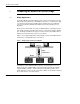
Modbus to Ethernet Bridge Figure 2 shows a typical application in which three Bridges join Modbus networks through a common Ethernet link. Figure 2 Bridging Between Multiple Modbus Networks Modbus Ethernet Bridges (3 units) 174 CEV 300 10 Modbus Modbus 1.1.2 Overview: Installation and Configuration The Bridge is designed for easy ‘snap’ mounting on a standard DIN rail. Its front panel has connectors for power, ground, Ethernet and Modbus cables.
Modbus to Ethernet Bridge 1.2 Mapping Modbus and IP Addresses The Bridge maps messages between Modbus and IP addresses according to the type of device you have configured at its Modbus port. 1.2.1 Mapping for a Modbus Master When you configure a Modbus Master device at the Bridge’s serial port, you can assign up to eight entries into an internal mapping table that is maintained in the Bridge’s memory. You enter your intended mapping into the table during your configuration of the Bridge.
Modbus to Ethernet Bridge Figure 3 shows an example of message address mapping between a Modbus Master and a Modbus Slave using two Bridges with an Ethernet link. Figure 3 Mapping Modbus and IP Addresses Modbus Master Modbus message to Slave address 10 Bridge A Ethernet Modbus – IP Address Mapping Entry: 192.168.001.024 Bridge 010 : 192.168.001.024 B Modbus Slave(s) Bridge routes message to Slave according to user–defined setup: Message Slave Address (10) or Fixed Slave Address (1 ...
Modbus to Ethernet Bridge 1.
Modbus to Ethernet Bridge Table 1 Front Panel Components (See Figure 4) Item 1 Component Wire terminal Name RxD or Rx – 2 Wire terminal CTS or Rx + 3 Wire terminal RTS or Tx + 4 Wire terminal TxD or Tx – 5, 6, 7 8 9 10 Wire terminal Wire terminal Reset switch LED (Red) 11 LED (Green) NC GND RST Fault or Configuration Ready 12 LED (Yellow) Active Ethernet 13 LED (Green) Link Good 14 Connector (RJ45) Ethernet port 15 Connector (RJ45) Modbus port 16 LED (Yellow) Modbus Tx 17
Modbus to Ethernet Bridge 1.4 Specifications Table 2 Power Parameter Operating Power, Nominal Operating Power Range Maximum Power Drain Connection Fuse Specification 12 or 24 V dc 9 ... 30 V dc 3W Screw terminals External, supplied by customer.
Modbus to Ethernet Bridge Table 6 Packaging Parameter Dimensions Enclosure Material Weight, Product Weight, Shipping Mounting Method Table 7 Description 35 x 95 x 60 mm (1.4 x 3.7 x 2.4 in) High–impact plastic 0.5 kg (1.0 lb) 0.9 kg (2.
Installing the Bridge Hardware H Mounting the Bridge on the DIN Rail H Connecting the Power Wiring H Connecting the Serial Cable (RJ45 Port) H Compatible Modbus Devices and Cables H Modbus Cable Pinouts H Connecting the Serial Cable (Wiring Terminals) H Setting the Serial Port Switch H Connecting the Ethernet Cable 2 19
Installing the Bridge Hardware 2.1 Mounting the Bridge on the DIN Rail 2.1.1 Before You Install the Bridge The Bridge has an Ethernet MAC address printed on the label on its side panel. The address is required for your Ethernet network administrator to configure the Bridge. Before you install the Bridge on the DIN rail, write down the MAC address and give it to your network administrator. The label may not be visible after you install the Bridge.
Installing the Bridge Hardware 2.2 Connecting the Power Wiring Figure 6 shows the connections for operating power and ground. Operating power must be fused externally to the Bridge. The Bridge draws 3W maximum (9 ... 30 V dc). Select a fuse value according to the supply voltage. Figure 6 Connecting the Power Wiring 9 ...
Installing the Bridge Hardware 2.3 Connecting the Serial Cable (RJ45 Port) Figure 7 shows serial cable connections for several Modicon CPUs for operation as Modbus Master or Slave devices. The figure also shows a typical connection to a standard PC 9–pin serial port for setting up the Bridge configuration. Table 8 lists other compatible devices and cables.
Installing the Bridge Hardware 2.4 Compatible Modbus Devices and Cables The Bridge connects directly by RJ45 cable to various products shown in Figure 7. Table 8 below lists other Modbus devices and their cable connections to the Bridge. Connections are RS–232 unless indicated otherwise. Cable pinout references are to the diagrams in Figure 8 on page 24.
Installing the Bridge Hardware 2.5 Modbus Cable Pinouts References in this figure are to the devices listed in Table 8 on page 23.
Installing the Bridge Hardware Figure 9 shows the layout of DB9–RJ45 and DB25–RJ45 Adapter Kits available from Schneider Automation. Each kit contains three jumper wires and a pin insertion tool. Follow the pinout diagrams in Figure 8 for assembling the adapter for your product.
Installing the Bridge Hardware 2.6 Connecting the Serial Cable (Wiring Terminals) Figure 10 shows the connection for serial cables at the Bridge’s wiring terminals.
Installing the Bridge Hardware 2.7 Setting the Serial Port Switch Figure 11 shows the front panel switch for setting the Bridge’s serial port interface. Before you place the Bridge into service, set the switch for the type of interface used in your application: H UP: RS–232 interface. H DOWN: RS–422 or RS–485 interface. Figure 11 Setting the Serial Port Switch Serial Port Switch UP: RS–232 DOWN: RS–422 or RS–485 Warning COMMUNICATION DISRUPTION HAZARD The serial port switch is a hardware function.
Installing the Bridge Hardware 2.8 Connecting the Ethernet Cable Figure 12 shows the RJ45 port connection for the 10baseT Ethernet cable. Figure 12 Connecting the Ethernet Cable Ethernet Port (RJ45) Warning COMMUNICATION DISRUPTION HAZARD Connecting any device to an active Ethernet network can disrupt communication on the network. Before you connect the Bridge to your network, and before you apply power to the Bridge, heed the steps in Chapter 3 for configuring the Bridge in your application.
Configuring the Bridge H Before You Start H Connecting by the RS–232 Port H Connecting by Telnet (IP Address Not Assigned) H Connecting by Telnet (IP Address Assigned) H Using the Configuration Menu H Option 1: Network/IP Settings H Option 2: Serial and Mode Settings H Option 3: Modem Control Settings H Option 4: Advanced Modbus Protocol Settings H Option 5: Unit_ID to IP Address Mapping Table 3 29
Configuring the Bridge 3.1 Before You Start 3.1.1 Configuration Overview Your Bridge must be configured to match your system application. Before you start to configure the Bridge, get the Bridge’s Ethernet and serial port parameters from your network administrator. Here is your check list for obtaining the configuration information: 3.1.2 H Ethernet IP address. H Ethernet Gateway address, if applicable to your Bridge’s network. H Serial port interface: RS–232, RS–422, RS–485.
Configuring the Bridge 3.2 Connecting by the RS–232 Port To configure the Bridge at its local RS–232 port, use a serial terminal emulation program and a modem cable. See Figure 7 for a connection example. Regardless of any serial parameters currently set into the Bridge for a user application, it will always use the following parameters for setup: 9600 baud, 8 data bits, No parity, 1 Stop bit (9600,8,N,1). Set your emulator to these parameters.
Configuring the Bridge Connecting by Telnet (IP Address Not Assigned) 3.3 If the Bridge does not yet have an IP address stored in its memory, you can establish an initial connection using its MAC address. This will allow you to access the Bridge’s Configuration Menu, assign an IP address, and make it persistent in the Bridge. If you are not sure about whether your Bridge has a stored IP address, you must connect at its serial port and access its Configuration Menu. Section 3.
Configuring the Bridge 3.4 Connecting by Telnet (IP Address Assigned) If the Bridge already has an IP address stored in its memory, and you know that address, you can establish a Telnet connection to the Bridge using port 9999. If you do not know the IP address currently stored in the Bridge, you can find that address by connecting to the Bridge’s serial port and accessing its Configuration Menu. Section 3.2 describes how to connect to the serial port.
Configuring the Bridge 3.5 Using the Configuration Menu When the Bridge enters its configuration mode it displays its opening screen: Schneider Automation, Inc. – Modbus Bridge (174 CEV 300 10) Serial Number 101–161 Software Version V01.00 (990402) Press Enter to go into Setup Mode, wait to close At this screen, press to see the Configuration Menu. 3.5.1 Configuration Menu The Configuration Menu shows the Bridge’s current settings.
Configuring the Bridge 3.5.3 Configuration Options: 1 ... 5 These are your configuration options. Each option is described in detail in the following sections of this book: 3.5.4 H 1) Network/IP Settings: H 2) Serial & Mode Settings: See Section 3.7. H 3) Modem Control Settings: See Section 3.8. H 4) Advanced Modbus Protocol Settings: H 5) Unit ID –> IP Address Table: See Section 3.6. See Section 3.9. See Section 3.10.
Configuring the Bridge 3.6 Option 1: Network/IP Settings When you select option 1 on the Configuration Menu, the Bridge displays its current Ethernet settings. Here is an example: IP Address : (192) .(168) .(001) .(023) Set Gateway IP Address (Y): Gateway IP Address : (192) .(168) .(001) .(030) Set Netmask (N for default) (Y): (255) .(255) .(255) .(000) IP Address The four entry fields for the IP address are shown as parenthesis ( ).
Configuring the Bridge 0xFFFFFF00 or 255.255.255.0, using the lower 8 bits for the host part of the IP address. This allows up to 255 devices on the local subnetwork. This default mask is the example shown in the menu above. If the user desires to have multiple subnetworks with up to 32 devices on each the subnetwork mask could define 5 “host” bits or 255.255.255.224.
Configuring the Bridge 3.7 Option 2: Serial and Mode Settings When you select option 2 on the Configuration Menu, the Bridge displays its current serial port settings. Here is an example: Attached Device (1=Slave, 2=Master) (001): Serial Protocol (1=Modbus/RTU, 2=Modbus/ASCII) (001): Interface Type (1=RS232, 2=RS422, 3=RS485) (001): Enter Serial Parameters (9600,8,E,1): Attached Device Identify the type of Modbus device (Slave or Master) attached to the Bridge’s serial port. The default is Slave.
Configuring the Bridge 3.8 Option 3: Modem Control Settings When you select option 3 on the Configuration Menu, the Bridge displays: RTS/CTS Mode (1=Fixed, 2=Variable) (001): RTS/CTS Mode RTS (Request to Send) and CTS (Clear to Send) are serial port signals that coordinate the starting and stopping of data requests between the Bridge and its port device. You can customize the RTS/CTS mode. The options are: Fixed or Variable. The default is Fixed.
Configuring the Bridge 3.9 Option 4: Advanced Modbus Protocol Settings When you select option 4 on the Configuration Menu, the Bridge displays parameters for the type of Modbus device (Slave or Master) at its serial port. Slave Device: Slave device parameters are: Slave Address (0 for auto, or 1...
Configuring the Bridge Allow Modbus Broadcasts This parameter specifies whether the Bridge may allow a Modbus Broadcast message to be sent to Slave devices at its serial port, or not allow those messages. Broadcast messages are those received by the Bridge containing a Unit_ID of 0 (zero). If Modbus Broadcasts are allowed, broadcast messages are passed to the serial port as received with the Unit_ID contents of 0 (zero).
Configuring the Bridge 3.10 Option 5: Unit ID to IP Address Mapping Table If you have specified the Bridge’s serial port Attached Device parameter as a Modbus Master (see Section 3.7), you will need to map the Slave addresses received in messages from that Master to their intended IP address destinations. The Bridge maps the one–byte Modbus Slave address to an IP address for delivery on Ethernet. 3.10.1 How the Address Mapping Works The Bridge contains an address mapping table with eight entries.
Configuring the Bridge 3.10.3 Entering New Address Mapping When you select option 5 on the Configuration Menu, the Bridge displays it current mapping. Then it prompts: A)dd, D)elete, E)xit –– select function: Adding a New Map Entry Press A to add a new entry into the mapping table. The Bridge will prompt you to enter the new mapping values. The values will go into the first available (empty) table location.
Using Panel Software H Using Concept or Modsoft H Using Other Software 4 45
Using Panel Software 4.1 Using Concept or Modsoft 4.1.1 Software Versions To support Modbus/TCP to the Bridge, you need Concept version 2.1 or later, or Modsoft version 2.6 or later. Set the communications parameters as follows: H Protocol: TCP/IP H Dest_Port: 502 H Dest_Index: Modbus Slave address Note that the Bridge contains an internal Slave Address configuration option which might affect the delivery of messages to a Slave device at its serial port.
Using Panel Software 4.2 Using Other Software 4.2.1 Intellution FIX MMI The Bridge allows Windows workstations with Intellution FIX software to access Modbus devices by TCP/IP over Ethernet. The current version of this software does not support the Modbus/TCP Unit_ID field. Therefore if you have configured the Bridge for a Slave device at its serial port, you must configure the Bridge’s internal Slave Address parameter for that device. This restricts the Bridge to a single Slave device at its port.
Glossary 5 address On a network, the identification of a station. In a frame, a grouping of bits that identifies the frame’s source or destination. API Application Program Interface. The specification of functions and data used by one program module to access another; the programming interface that corresponds to the boundary between protocol layers. ARP Address Resolution Protocol.
Glossary default gateway The IP address of the network or host to which all packets addressed to an unknown network or host are sent. The default gateway is typically a router or other device. DHCP Dynamic Host Configuration Protocol. A network protocol used to configure IP addresses dynamically. DHCP is an extension of BOOTP. DNS Domain Name System. A protocol within TCP/IP used to find IP addresses based on host names.
Glossary ICMP Internet Control Message Protocol. A protocol within TCP/IP used to report errors in datagram transmission. Internet The global interconnection of TCP/IP based computer communication networks. IP Internet Protocol. A common network layer protocol. IP is most often used with TCP. IP Address Internet Protocol Address. A 32–bit address assigned to hosts using TCP/IP. layer In the OSI model, a portion of the structure of a device which provides defined services for the transfer of information.
Glossary repeater A device that connects two sections of a network and conveys signals between them without making routing decisions or filtering packets. router A device that connects two or more sections of a network and allows information to flow between them. A router examines every packet it receives and decides whether to block the packet from the rest of the network or transmit it. The router will attempt to send the packet through the network by the most efficient path.
Glossary UDP User Datagram Protocol. A protocol which transmits data over IP. URL Uniform Resource Locator. The network address of a file. UTP Unshielded Twisted Pair. A type of cabling consisting of insulated cable strands which are twisted together in pairs. Winsock The Microsoft implementation of the Windows Sockets networking API based on the Berkeley UNIX Sockets interface for supporting TCP/IP. WWW World Wide Web.
Modicon, Square D and Telemacanique are PLC brand names from Schneider. These products are sold in the US by Square D; in Canada, Latin America, Europe, Asia, Asia/Pacific and Middle East by Schneider; in Germany by AEG Schneider Automation; in China and Persian Gulf by Schneider Automation; in South Africa by ASA Systems Automation; in Austria by Online. United States: Schneider Automation, Inc.