
- Quantum Cascade Laser Starter Kit Instructions Manual

Starter Kit Instruction Manual Maintenance 51
Current adjustment
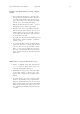
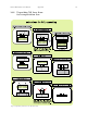
[28] Set the selector (3) to mode Setting
◦
C
and adjust the temper ature value to 25
◦
C
by means of the Set Temperature 5 tuns
portentiometer P8 (2).
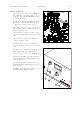
[29] On the external power supply, rise slowly
the voltag e to 30 V and the current to 1.5 A.
,→ The tension should stabilize at 30 V
Note: If the current is too high, stop the test
and verify the transistors Q1 to Q4 (1) and
their associated resistors.
There might be a soldering problem. In this
case, fix it and repeat the procedure from step
[10].
[30] Set the selector (3) to mode Real I.
,→ Value displayed: ≤ 1A.
[31] Set the selector (3) to mode Real
◦
C.
,→ Value displayed should tend to the defined
value.
[32] Wait for a certain time and check the
Peltier tempera ture with a thermometer
[33] Set the selector (3) to mode Setting +I.
[34] Increase the limit of positive current to
3.5A by means of the +I trimmer (4) located
on the front panel.
[35] Increase the limit of negative current to
5A by means of the -I trimmer (5) located on
the front panel.
[36] Change the temp e rature reference to -25
◦
C and check the displayed current.
1
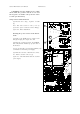
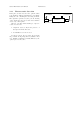
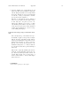
Fig.47: TCU 151 main board
TCU151
T
e
m
p
e
r
a
t
u
r
e
C
o
n
t
r
o
l
l
e
r
A
l
a
r
m
R
e
s
e
t
E
x
t
e
r
n
a
l
I
n
t
e
r
n
a
l
R
e
a
l
I
R
e
a
l
C
S
e
t
t
i
n
g
C
S
e
t
t
i
n
g
+
I
S
e
t
t
i
n
g
−
I
+
−
5
4
3
2
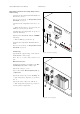
Fig.48: TCU 151 front panel