
- Quantum Cascade Laser Starter Kit Instructions Manual


Starter Kit Instruction Manual Description 21
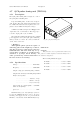
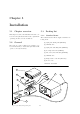
4.6 QCL pulse switching measuring unit
4.6.1 Generalities
The measuring circuit c ontained in the LDD100
provides information about various laser pulse pa-
rameters (peak voltages, supply voltages, duty cy-
cle, frequency). They are only estimated values,
since exact mea surement of short and s trong pulses
with diodes and averaging circuitry is difficult.
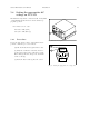
Keep in mind that you should always measure
the voltages on the LLH100 if you need accurate
time and voltage data (see final paragraph). How-
ever, these data are useful for monitoring and surveil-
lance purposes, and to give a rough estimation of
the current parameters.
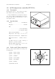
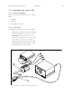
4.6.2 Measured voltages
• UHV: 1/2 of the average voltage, respective
to VHT (user supplied high voltage)
• ULH: 1/2 of the average laser anode voltage,
respective to VHT
• ULL: duty cycle dependent p eak lase r cathode
voltage, respective to VHT
• UD: duty cycle dependent peak transistor drain
voltage, respective to VHT
• UPI: 1/2 average internally reshaped drive volt-
age, respective to ground
• UPT: 1 /2 average of a 37ns fixed length pulse,
respective to ground
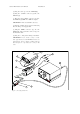
4.6.3 Timing data
Pulse frequency calculation
UPT can be used to calcula te the pulse fr e quency
as follows:
f = f
0
2UP T −ν
P low
ν
P high
−ν
P low
Where f
0
is a frequency constant, v
P low
and
v
P high
are the TTL pulser voltage limits.
Actual values: f
0
=
1
37
ns , v
P low
=0.01V, v
P high
=5V