Quantum Cascade Laser Starter Kit Instructions Manual (Web version) CAUTION Before using the Quantum Cascade Laser Starter Kit, read this documentation and take special note of all safety instructions
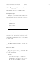
Contents 1 Identification 1.1 Document . . . . . . . . . . . . . . . . . . . . . . . . . . . . . . . . . . . . . . . . . . . . . 1.2 Limited waranty . . . . . . . . . . . . . . . . . . . . . . . . . . . . . . . . . . . . . . . . . 4 4 4 2 General 2.1 Chapter overview . . . . . 2.2 Generalities . . . . . . . . 2.3 Compliance . . . . . . . . 2.3.1 Laser compliance . 2.4 Glossary . . . . . . . . . . 2.4.1 Persons . . . . . . 2.4.2 Product . . . . . . 2.5 Typographic conventions . . . . . . . . . . . . . .
2 . . . . . . . . . . . . . . . . . . . . . . . . . . . . . . . . . . . . . . . . . . . . . . . . . . . . . . . . . . . . . . . . . . . . . . . . . . . . . . . . . . . . . . . . . . . . . . . . . . . . . . . . . . . . . . . . . . . . . . . . . . . . . . . . . . . . . . . . . . . . . . . . . . . . . . . . . . . . . . . . . . . . . . . . . . . . . . . . . . . . . . . . . . . . . . . . . . . . . . . . . . . . . . . . . . . . . . . . . . . . . . . . . . . . . . . . . . . . . . . . . . .
3 10 Appendix 10.1 Bias Circut (”Bias-T”) . . . 10.1.1 General . . . . . . . 10.1.2 Description . . . . . 10.1.3 Specifications . . . . 10.1.4 Utilisation . . . . . . 10.2 Unpacking NS laser from its . . . . . . . . . . . . . . . . . . . . . . . . . . . . . . . . . . . . . . . . . . . . . . . . . . . . . . . transportation box . . . . . . . . . . . . . . . . . . . . . . . . . . . . . . . . . . . . . . . . . . . . . . . . . . . . . . . . . . . . . . . . . . . . . . . . . . . . . . . . . . . .
Chapter 1 Identification 1.1 Document Quantum Cascade Laser Starter Kit Instructions Manual. Web Version 3.1 02.07 Manufacturer Alpes Lasers SA 1-3 Passage Max-Meuron CP 1766 CH-2001 Neuchâtel Tel. ++41 32 7299510 Fax. ++41 32 7213619 http://www.alpeslasers.ch info@alpeslasers.ch 1.2 Limited waranty Alpes Lasers SA will accept no responsibility for problems arising out of incorrect use of the instrument.
Chapter 2 General 2.1 Chapter overview This chapter gives basic information on system functions, specifications and documentation. 2.2 Generalities The indications in the present Instructions Manual, in particular the safety instructions must be complied with. 2.3 Compliance The Quantum Cascade Laser Starter Kit has been designed to meet all current safety at work and operating requirements. 2.3.1 Laser compliance The system described in this manual contains a laser device.
Starter Kit Instruction Manual 2.4 General Glossary The following terms, among others, are used in this Instructions Manual. 2.4.1 Persons Personnel Personnel refers to all persons who carry out any activity with the instrumentation and meet the manufacturer’s requirements about personnel to run those activities and have been therefore authorized. 2.4.2 Product QCL This is the Quantum Cascade Laser manufactured by Alpes Lasers SA, CH-2001 Neuchâtel.
Starter Kit Instruction Manual 2.5 General Typographic conventions The following styles are used in this manual. Description style This style, used in relation with a number in illustrations (figures) is preceded by the corresponding number: Example: (1) First item. (2) Second item. (3) etc...
Starter Kit Instruction Manual General Procedure effects style The procedure effects are described by using the following symbol ,→. Example: [1] Click on the Delete Sample icon. ,→ The message Do you really want to delete the sample ? appears. Cross references style This style is used to help the personnel to find other information about the current subject. Example: See page x-y.
Starter Kit Instruction Manual General Note style Used when the personnel attention must be drawn to a particular operation or information. Example: Note: The laboratory housing LLH100 makes available two outputs giving access to these voltage. Caution style Used to prevent the personnel from any danger or hazardous situation. Non-compliance with such instructions may lead to damage parts or environment. Example: CAUTION ! Take care about...
Chapter 3 Safety Instructions 3.1 Chapter overview This chapter sets out safety instructions for ensuring safe and trouble-free operation of the system described in this manual. 3.2 3.2.1 Introduction Principle The personnel must have read and understood this documentation before carrying out any activity whatsoever with the system described in this manual. In case of unclear information, please contact the manufacturer or Alpes Lasers SA representative. 3.2.
Starter Kit Instruction Manual 3.3 Safety Instructions General safety instructions • Never attempt to use a system for purposes other than those detailed in this manual. • Never attempt to use a system in conjunction with other instruments without obtaining prior information and approval from the manufacturer. • Never attempt to use spare parts other than those supplied by the manufacturer.
Chapter 4 Description 4.1 Chapter overview 4.2 System Composition For operation of the system, the user must provide a stabilized DC power supply capable of deThis chapter gives a basic description of the Quan- livering DC current that corresponds to the laser tum Cascade Laser Starter Kit system and its com- peak current multiplied with the specified duty cyposition. cle at the specified LDD100 voltage: refer to the datasheet of the laser.
Starter Kit Instruction Manual 4.3 4.3.1 Description 13 DFB and FP Quantum Cascade Lasers Description Quantum Cascade Lasers (QCL) are unipolar lasers emitting in the mid-infrared from 4 to 17 microns. The laser is a ridge of InGaAs and AlInAs grown on InP providing gain and a Fabry-Perot cavity in order to build the laser oscillation up. DistributedFeedback(DFB) Quantum Cascade Lasers are then obtained by adding a grating, forcing the laser to emit at the target wavelength. 4.3.
Starter Kit Instruction Manual 4.3.3 Description 14 Specifications Far field elliptical (FWHM): Vertical: . . . . . . . . . . . . . . . . . . . . . . . . . . . . . . . . . . . . . . . . . . . . . . . . . . . . . . . . . . . . . . . . . . . . . . . . . . . . . . . .60◦ Horizontal: . . . . . . . . . . . . . . . . . . . . . . . . . . . . . . . . . . . . . . . . . . . . . . . . . . . . . . . . . . . . . . . . . . . . . . . . . . . . .
Starter Kit Instruction Manual 4.3.4 15 Description Electrical model The QCL can be modelised in a RC circuit. Electrical model characteristics − + = − The values given below apply for a 10µm laser wavelength. R1 C1 + C2 Fig.5: Electrical model of QCL Note: Voltage and resistor values may vary according to the type of laser. R1 : . . . . . . . . . . . . . . . . . . . . . . . . . . . . . . . . . . . . . . . . . . 10 to 20Ω when a voltage of 4 to 6 Volts is applied R1 : . . . . . . . . . . . .
Starter Kit Instruction Manual 4.4 16 Description Laboratory Laser Housing(LLH100) 4.4.1 Description The Laboratory Laser Housing is a Thermo-Electric cooled box which encapsulates the Quantum Cascade Laser. 1 The internal temperature is controlled by a PT100 sensor and heat is dissipated by air or water. The LLH100 is designed to ease the laser installation or replacement.
Starter Kit Instruction Manual 17 Description LLH100 internal view The Laboratory Laser Housing includes the following items: 1 (1) LLH100 top cover (2) PET U-shaped holder (3) Gilded copper contact (UP and DN) (4) Laser (5) Laser receptacle 4.4.2 Specifications 2 Maximum Peltier current (with water cooling): . . . . . . . . . . . . . . . . . . . . . 5A 3 Lowest reachable temperature (with water cooling): . . . . . . . . . . . . . . . . .
Starter Kit Instruction Manual 4.4.3 18 Description Thermo-Electric Cooler (TEC) and PT100 connections The pin 1 is recognised by a circle around it and a thin noon ended circle starts from pin one and turns around the pins until pin 6. 6 1 (1) Pin 1: +Peltier element (2) Pin 2: - Peltier element (3) Pin 3: I+ PT100 5 2 (4) Pin 4: Sens + PT100 (5) Pin 5: Sens - PT100 (6) Pin 6: I- PT100 4 3 Specifications of the Peltier connector Vacuum case plug reference: . . . . . . . LEMO # HGG.1b.306.CLLPV.
Starter Kit Instruction Manual 4.4.4 Description Measurement connection These connections give access to the voltage on the laser. The ”L” connection is connected AC coupled to the cathode of the laser through a divider by ten. The end of cable must be 50Ω terminated for accurate measurement. The ”B” is connected the same to the anode of the laser (Base Receptacle). By using the math trace of an oscilloscope showing the ”L” channel minus the ”B”, one can get the voltage on the laser.
Starter Kit Instruction Manual 4.5 20 Description QCL pulser switching unit(LDD100) 4.5.1 Description The switching unit is based on dedicated power MOS-FETS with up to 30A current compatibilities and 60V. In addition, the circuit is limited in power dissipation by the cooling of the unit. During operation, the temperature of the case should not exceed 60C. While powering usual QC diodes, these limitations are never reached because the laser has usually much lower power ratings.
Starter Kit Instruction Manual 4.6 4.6.1 Description QCL pulse switching measuring unit Generalities The measuring circuit contained in the LDD100 provides information about various laser pulse parameters (peak voltages, supply voltages, duty cycle, frequency). They are only estimated values, since exact measurement of short and strong pulses with diodes and averaging circuitry is difficult.
Starter Kit Instruction Manual Description Duty cycle calculation UPI can be used to calculate the duty factor as follows: df = 2UP I−νP low νP high −νP low with vP low and vP high as above. To get the real duty cycle, df must be corrected as follows: I−νP low dc = fLDD df = fLDD ν2UP P high −νP low to compensate for systematic errors in the LDD100. Actual value is fLDD = 1.1 4.6.
Starter Kit Instruction Manual 4.6.5 Description Laser peak voltage The laser peak voltage is given by: Upeak = 2U LH − U LLpeak where U LLpeak is the corrected peak value of ULL as calculated in the previous paragraph. 4.6.6 Average dissipation The average thermal dissipation of the laser is given by: P = Upeak Ipeak dc where Upeak and Ipeak are the peak values of laser voltage and current as calculated in the previous paragraphs, and dc is the (corrected) duty cycle. 4.6.
Starter Kit Instruction Manual 4.7 24 Description QCL pulser timing unit (TPG128) 4.7.1 Description The QCL pulser timing unit is designed to control the QCL pulser switching unit. It provides TTL pulses on 50Ω on two independent outputs. The pulse duration is adjustable from 0 to 200ns. The interval between pulses can be adjusted between 200ns and 105µs in 3 ranges. OF F A TTL level Gate in input and Trigger out output have also been included. The trigger precedes the output pulse by about 100ns.
Starter Kit Instruction Manual 4.8 25 Description QCL temperature controller(TCU151) 4.8.1 Description The TCU151 is used to control the laser’s temperature inside the Laboratory Laser Housing. It uses a PT100 sensor to measure the temperature of the cold plate and maintains a pre-set temperature either from a front panel knob or from a user supplied voltage. 4.8.2 Specifications Voltage: . . . . . . . . . . . . . . . . . . . . . . .
Chapter 5 Installation 5.1 Chapter overview 5.3 Packing list This chapter describes the installation and the con- 5.3.1 Standard items nection of the QCL Starter Kit. It also explains the The standard starter Kit is supplied with the foloperating checks before the normal use. lowing items: 5.2 General (1) QCL pulse timing unit (TPG128) The setup procedures outlined below must be followed meticulously to ensure that QCL Starter Kit operates correctly and safely.
Starter Kit Instruction Manual 5.4 27 Installation Setting the appropriate AC voltage on TCU151 The TCU151 temperature controller works on 110/120V or 220/240V if the fuse holder is oriented in the appropriate position. Note: There are two rates: MO N 10 ITOR mV IN /CG MaUTP x: 15 U T V/6A 110-120V, 60Hz (USA) USE ONLY FUSE UNIQ S WITH / EMP DES UEM 250V 110− FUSI ENTLOYE 120V BLES AVEC R DE 250v 220− 240V 5.4.
Starter Kit Instruction Manual 5.5 28 Installation Installing the starter Kit 5.5.1 Before beginning Make sure that the following devices are turned OFF: • TPG128 • TCU151 • User DC power supply 5.5.2 Procedure To install the QCL Starter Kit, proceed as follows: [1] Plug the low impedance line into the LLH100 connector (2). The line connector is coded. CAUTION ! Pay attention about the connection’s polarity. The laser must be floating from ground for both anode and cathode.
Starter Kit Instruction Manual 29 Installation [3] Plug the cable (3) onto the LDD100(4). [4] Plug the +12VDC connector (1) into the TPG128 (9). [5] Plug the trigger BNC connector (2) into the TPG128 (9) Out 1 or Out 2 outptut. CAUTION ! The unit must be floating. [6] Plug the banana cables (8) (red and black) into the DC power supply unit. [7] Plug the LEMO connector (6) onto the LLH100 module (5) and the connector (7) onto the TCU151 unit. [8] Plug the cooling water tubing if available.
Chapter 6 Use 6.1 Chapter overview This chapter describes how to use the QCL Starter Kit. It also explains the functionalities of the TPG128 and the Temperature Controller (TCU151). 6.2 QCL pulse timing unit command description The Quantum Cascade Laser is controlled by the QCL pulse timing unit TPG128. The TPG128 front panel is composed of the following items: (1) Power ON/OFF switch. (2) Period fine 10 turns potentiometer. (3) Period range 3 positions switch.
Starter Kit Instruction Manual 6.3 31 Use TCU151 command description The internal temperature of the LLH100 is driven by the TCU151 unit. The Temperature Controler front and rear panels are composed of the following items: 1 (1) Set Temperature 5 turns potentiometer: Allows to set the internal temperature reference. 2 3 (2) LCD 3 digits display: Used to display either the actual sensor or reference temperature/current. (3) Switch to select which temperature or current signals to display.
Starter Kit Instruction Manual 6.4 32 Use Laser utilisation 6.4.1 Overview In order to insure a correct use and and an appropriate lifetime to the laser, it is recommended to proceed according a specific order as below: 1 • Start water flow to cool the LLH100. 2 • Turn on the temperature controller and set the desired temperature. 3 • Start the pulse generator. • Switch on the power supply. 6.4.
Starter Kit Instruction Manual 33 Use [5] Turn the TPG128 ON (8) and set the pulse period to 2.0 and the range to 0.5 to 10.5 µs (medium), corresponding to a period length of about 2.5us, or to the values specified on the datasheet or by Alpes Lasers. [6] Set the pulse duration (11) to 3.0, corresponding to a pulse length of about 50ns, or to the values specified on the datasheet or by Alpes Lasers.
Starter Kit Instruction Manual 6.5 34 Use Interlock utilisation The temperature controller is designed with an builtin interlock (1). This function is activated when a fault occurs on the TCU151 controller (over-temperature, over-current, etc.). Zin :1 Mo hm 0 The interlock is by default a NC (Normally Close) relay contact. CAUTION ! It is also possible to set the Interlock as a NO (Normally Open) contact. For more details about the settings, see the procedure on page 42. 6.5.
Chapter 7 Troubleshooting 7.1 Chapter overview This chapter sets out troubleshooting instructions for ensuring safe and trouble-free operation of the Quantum Cascade Laser Starter Kit system. 7.2 Principle The personnel must have read and understood this documentation before carrying out any activity whatsoever with the Quantum Cascade Laser Starter Kit. In case of unclear information, please contact the distributor.
Starter Kit Instruction Manual Troubleshooting Laser draws current but gives no light - The laser may be reversed polarized (it is not a desirable situation but does generally not destroy the laser). √ Check the polarity of the connection. - The polarity is right. It draws too much current and the power meter is misaligned. √ Reduce the current at the maximum specified for the operating temperature. √ Check power meter alignement and scale. - The QCL laser is not used with the LLH and is grounded.
Chapter 8 Maintenance 8.1 Overview This chapter describes all procedures of maintenance and calibration for the QCL starter Kit. The procedures described herein must be performed by personnel trained on the electronic field, with acceptance by Alpes Lasers, otherwise the warranty will be lost. Note: The TTL Pulse Generator (TPG128) and the Temperature Controller (TCU151) are calibrated in factory. 8.1.
Starter Kit Instruction Manual 8.2 38 Maintenance Replacement procedures 8.2.1 Quantum Cascade Laser replacement Before beginning [1] Switch the QCL Starter Kit OFF 1 Material needed • 1 set of Allen keys. • 1 ohmmeter. • 1 QCL laser. • a pair of tweezers.
Starter Kit Instruction Manual 39 Maintenance [4] Install the new laser (4) into the holder using small tweezers ( 0.5cm aperture). [5] Hold the laser (4) on the gilded ceramic pads with the tweezers pins along the axis of the largest length of the copper submount. 1 [6] Place it in the receptacle parallel to the window. ! Warning ! Avoid hitting the laser chip facet on the case, it is extremely fragile. 2 5 [7] Place the screws (3) in the PET holder (5).
Starter Kit Instruction Manual 8.2.2 Maintenance QCL ”UP” and ”DN” position exchange Before beginning [1] Switch the QCL Starter Kit OFF. 1 Material needed • 1 set of Allen keys. • 1 ohmmeter. • 1 FP-QCL laser contact plate. • 1 pair of tweezers. 2 Procedure To exchange the beam of a Quantum Cascade Laser, proceed as follows: [1] Remove the top cover (2) of the Laboratory Laser Housing (LLH100) by unscrewing the screws (1).
Starter Kit Instruction Manual Maintenance [5] Place the screws (3) in the PET holder (4). [6] Place the PET holder (4) on the two guides (5) on the back of the laser receptacle (6) being careful of maintaining the PET holder higher on the laser side than on the back side. 1 [7] Once the holder (4) is engaged in the guides, push it down until contact with the gilded ceramic pads of the laser is established. [8] Screw the PET holder (4) to the receptacle (6).
Starter Kit Instruction Manual 8.3 42 Maintenance TCU151 temperature controller interlock setting 8.3.1 Generalities The interlock is located on the main board. Note: By default, the interlock is set to NC (Normally Close) contact. 8.3.2 Before beggining interlock setting [1] Switch the instrument OFF. 2 1 [2] Unplug the power cord. [3] Remove the cover (1) to acces the main board (2). TC Ala rm 8.3.
Starter Kit Instruction Manual 8.4 43 Maintenance Calibaration procedures 8.4.1 TPG128 calibration Generalities The present section describes procedure to be carried out for particular calibration of the TPG128. Before beginning 1 [1] Switch the instrument OFF. [2] Remove the cover (1). [3] Switch the instrument ON. ! WARNING ! Keep in mind that during the calibration, the instrument is alive (powered on) OF F Needed material ON Po we r max • 1 set of screwdriver. • 1 oscilloscope.
Starter Kit Instruction Manual 44 Maintenance [5] Choose the range 5 µs to 105 µs. Pot 10 turns Period on 10. Adjust the adjustable capacitor max 105 µs adj (4) in order to obtain a 105 µs long period. [6] Pot 10 turns Period on 0. Ajust the pot Period min adj (1) in order to have a period of 5 µs. [7] Repeat steps 5) and 6) in order to obtain 105 +/- 1 µs and 5 +/- 0,1 µs for the two settings of the pot Period. [8] Choose the range 0.2 µs to 2.2 µs. Pot 10 turns Period on 10.
Starter Kit Instruction Manual 45 Maintenance [12] Connect oscilloscope on the output Out1. Load with a 50Ω . Choose a repetition period of about 5 µs. [13] Pot 10 turns Duration on 10. Adjust capacitor Max duration (2) to have a output pulse of 200 ns +/-5 ns. [14] Pot 10 turns Duration on 0. Adjust the pot Out 0ns adj (1) in order that the output pulse is 0ns. The pulse is 0 ns long when its shape is triangular with an 1,1 V amplitude (half of the maximum value).
Starter Kit Instruction Manual 8.4.2 46 Maintenance TCU151 temperature controller calibration ! WARNING ! Keep in mind that during the calibration procedure, the instrument is powered on. Before beginning [1] Power off the instrument. [2] Open the TCU151 top cover (1) to access the TCU151 main board (2). 2 1 Material needed • Voltmeter HP3458A or equivalent. • Voltage source Keithley SMU237 or equivalent.
Starter Kit Instruction Manual 47 Maintenance Sensing level and range adjustement [4] Replace the cable connected to J8 (4) with the 100Ω 1% reference resistor in the following way: 1 2 Connect one side of the resistors to pins 1 and 2, the other side to pins 3 and 4. 3 [5] Measure the voltage on Zn3/R10 (3). 4 Note: The value should be: 5 - V = 1.22 to 1.25V. 6 [6] Measure the voltage at the intersection of R19/R35 (5).
Starter Kit Instruction Manual 48 Maintenance Temperature Reference offset adjustment [10] Adjust B13 (3) to 0.000 with P3 (4) [11] Set the temperature with the Set Temperature potentiometer (Fig.40 (7)) to +5 ◦ C ,→ The temperature reference signal B13 should be ≥4.3V [12] Set the temperature with the Set Temperature potentiometer (Fig.40 (7)) to -5 ◦ C ,→ The temperature reference signal B3 should be ≤4.
Starter Kit Instruction Manual 49 Maintenance Oscillator check 1 [15] Measure the frequency on the pin 7 of U13 (1). Note: The value is 28KHz + /- 3KHz Fig.42: TCU151 main board Current/Voltage ratio adjustment [16] Adjust the trimmer P4 (6) in order to read B4 = 0.6V (4). [17] Set the selector (5) to mode Setting +I. The LCD screen should display 1.00 A. Note: If it is not the case, adjust it with P2 (2). 2 [18] Adjust the trimmer P4 in order to read B4 = 3.0 V.
Starter Kit Instruction Manual 50 Maintenance CAUTION ! For the further steps of this check, limit the positive current to 1 A and the negative one with 1.2 A by means of the 5 turns potentiometer) Temperature limit threshold [21] Measure the voltage on pin 2 of U10 (1). Note: The value should be: 0.7V (= 70 ◦ C) (If needed, adjust it with the trimmer P9(2)). 1 [22] Power off the instrument. Starting the power section of the instrument.
Starter Kit Instruction Manual 51 Maintenance Current adjustment [28] Set the selector (3) to mode Setting ◦ C and adjust the temperature value to 25 ◦ C by means of the Set Temperature 5 tuns portentiometer P8 (2). [29] On the external power supply, rise slowly the voltage to 30 V and the current to 1.5 A. ,→ The tension should stabilize at 30 V 1 Note: If the current is too high, stop the test and verify the transistors Q1 to Q4 (1) and their associated resistors. There might be a soldering problem.
Starter Kit Instruction Manual 52 Maintenance Miscellaneous functions testing Temperature limit testing [37] Decrease the temperature limit threshold from 0.7 V to 0.3 V. Note: For more details, see Temperature limit threshold on page 50. [38] Increase the temperature reference to 35 ◦ C. ,→ When the threshold is overpassed, the red LED (1) in front panel should lit. TC Ala rm [39] Wait the real temperature drops 10 C below the threshold. ◦ Re set [40] Reset the instrument with the RESET button (2).
Chapter 9 Application notes 9.1 9.1.1 Detection techniques Direct absorption In a direct absorption measurement, the change in intensity of a beam is recorded as the latter crosses a sampling cell where the chemical to be detected is contained. This measurement technique has the advantage of simplicity. In a version of this technique, the light interacts with the chemical through the evanescent field of a waveguide or an optical fiber. 9.1.2 QC Laser Chemical Cell Detector Fig.
Starter Kit Instruction Manual 9.1.3 54 Maintenance Photoacoustic detection In the photoacoustic detection, the optical beam is periodically modulated in amplitude before illuminating the cell containing the absorbing chemical. The expansion generated by the periodic heating of the chemical creates an acoustic wave which is detected by a microphone.
Chapter 10 Appendix 10.1 Bias Circut (”Bias-T”) 10.1.1 General The Bias-T allows to apply a constant (DC) current to the laser in addition to the pulsed current (therefore a Bias-T is useless in CW mode). The current is drawn from the external (user supplied) power supply through the laser. This current can be controlled electrically.
Starter Kit Instruction Manual 10.1.3 Appendix Specifications Bias frequency . . . . . . . . . . . . . . . . Up to 100 Hz Achievable shift . . . . . . . . . . . . . . . . . . . . . . . . 0.1% Input voltage Uin . . . . . . . . . . . . . . . . . . . 0 to 3 V Input voltage threshold . . . . . . . . . . . . . . . . 0.6 V Input frequency Fin . . . . . . . . . . . . . . 0 to 1 kHz Input impedance Zin . . . . . . . . . . . . . . . . . . 100Ω Output Umon max . . . . . . . . . . . . . . . . . . . . . 2.
Starter Kit Instruction Manual Appendix Dangers and disadvantages of using a Bias-T circuit • Since a Bias-T only allows to heat the laser, the emission wavelength can only be increased (or emission wavenumber decreased), and output power will decrease with increased Bias current, due to the additional heating.
Starter Kit Instruction Manual Appendix • As a rule of thumb, the overall dissipated power (sum of DC Bias current dissipation and pulse current dissipation) must never be higher than the average dissipated power given by the highest current / voltage / temperature combination specified in the datasheet.
Starter Kit Instruction Manual 10.2 Appendix Unpacking NS laser from its transportation box Fig.