
User`s guide


Chapter 2
20
KEMF-4010 User’s
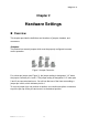
Jumper Settings
To ensure correct system configuration, the following section describes how to set
the jumpers to enable/disable or change functions. For jumper descriptions, please
refer to the table below.
Table 2 Jumper List
Label Function
JP1 COM6 Signal / Power Selection
JP2 COM4 Signal / Power Selection
JP3 COM2 Signal / Power Selection
JP4 DIO Signal / Power Selection
JP5 Parallel Port Signal Selection
JP6 COM5 Signal / Power Selection
JP7 COM3 Signal / Power Selection
JP8 ATX/AT mode Selection
JP9 Clear CMOS Selection
JP11 Panel Power Selection
JP12 Backlight Power Selection
JP13 COM1 Signal / Power Selection
JP14 KB / MS Signal Selection
JP15 BL Signal Selection
Table 3 JP1, JP2, JP3, JP6, JP7, JP13, COM Port Signal / Power Selection
Jumper Setting Function
1
1-3 Short Pin 1 = +12V
3-5 Short Pin 1 = +5V
5-7 Short Pin 1 = +5V
7-9 Short
Pin 1 = DCD@RS232, TX-@RS422,
DATA-@RS485 (Default)
2
2-4 Short Pin 9 = +12V
4-6 Short Pin 9 = +5V
6-8 Short Pin 9 = +5V
8-10 Short Pin 9 = RI (Default)
JP1,JP2,JP3,JP6,JP7 : Pitch: 2.54mm NY 6T[YIMTEX 3362*05SANGR]
JP13: Pitch: 2.54mm [YIMTEX 3322*05SAGR(6T]
Cable : 0C501P040926000L COM Port cable, 10-pin 2.54mm to DB-9 connector with bracket, L=26cm
Table 4 JP4, DIO Signal / Power Selection
Jumper Status
1-2 +5V(Default)
2-3 +12V
Pitch: 2.54mm [YIMTEX 3321*03SAGR(6T)]