
Installation Manual
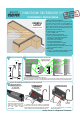

Secure Raceways to your furniture or walls surfaces using the
supplied Double Sided Tape, Screws, or both.
Double-Sided Tape: The desk or wall surface must be smooth
(no heavy texture), clean and dry. Measure, mark and cut the
Tape with Scissors. Apply the Tape to the back side of the
Raceway or Power Block Holder and press in place.
Caution: The adhesive is very stron g, and can pull paint or
finish off of the furniture or wall su rface when removed.
Screws: Use 2 Screws per Raceway section. Center your
Screws on the Alignment Groove, 0.25” from the edge (as
shown below) so that your Couplers cover the Screw heads .
Securing Raceways and Power Block Holders to
Furniture or Walls
0.25”
(6mm)
0.25”
(6mm)
Alignment
Centerline
Cutting
The components can be cut
using a Fine-Tooth Hacksaw
or PVC/ABS Pipe Saw.
Deburr all sharp edges.
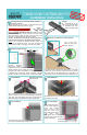
Butting Straight Sections
For straight runs of
Raceway (including
Power Block Holders),
butt them end-to-end, covering the seams with
Straight Couplers. If the Coupler fits loosely,
compress it (as shown) and reinstall. To cover seams bet ween
a Raceway and Power Block Holder, customize a Straight
Coupler to fit with a notch at the bottom- Contact us for details.
Do not fasten Raceways with their bottom resting directly on a desk, table or
counter surface. Leave a small space at the bottom to allow for insertion of
the Couplers. HINT: Use the Alignment Notc h on an Inside Elbow to get
correct spacing, as shown, for posit ioning the Raceway Alignment Grooves.
Raceways over Desk or Counter Surfaces
Leave a sm all space
between the desktop and
bottom of Raceway
Inside Elbows
Outside Elbows
90° Flat Elbows
270° Flat Elbows
Raceway Edge Locator Notches
Built-in to the Coupler
Before fastening the Raceways, hold the Coupler against the corner and
place a small pencil mark at eac h of the Raceway Edge Locator Notches
(pink circles). These marks identif y where to place your Rac eway ends.
Fasten the Raceways, insert the Cables and snap the Coupler in place.
Run the Raceway ends up to the corner edge (red arrow), insert the Cables
and snap the Coupler in place.
Run the tops corners of the Raceways to approximately the same point (red
arrow), ins ert the Cables and snap the Coupler in place.
Before fastening the Raceways,
hold the Coupler against the
surface, align centerline
notches, and place a small
pencil mark at eac h of the
Raceway Edge Loc at or Notches
( pink circles ). These
marks
Raceway Edge Locator Notches
Built-in to the Coupler
identify where to place your Raceway ends.
Fasten the Raceways, insert the Cables and
snap the Coupler in place.
J-Channel Raceway Cable Management System
Installation Instructions