UNDP-1 Universal Notebook Data Platform User Guide 80-VF329-3 Rev. A November 1, 2007 Submit technical questions at: https://support.cdmatech.com QUALCOMM Confidential and Proprietary Restricted Distribution. Not to be distributed to anyone who is not an employee of either QUALCOMM or a subsidiary of QUALCOMM without the express approval of QUALCOMM's Configuration Management.
Contents 1 Introduction 1.1 1.2 1.3 Documentation overview ....................................................................................... 6 Application description .......................................................................................... 7 Terms and acronyms............................................................................................. 11 2 External Connections 3 DC Power and UNDP Operating Modes 3.1 3.2 3.3 3.4 4 DC power source ..............................
UNDP-1 Universal Notebook Data Platform User Guide Contents Figures Figure 1-1 Figure 1-2 Figure 2-1 Figure 3-1 Figure 4-1 Figure 5-1 80-VF329-3 Rev. A UNDP-1 product deliverables.......................................................................... 8 Example application functional block diagram ............................................... 9 External connections...................................................................................... 14 DC power connections...........................
UNDP-1 Universal Notebook Data Platform User Guide Contents Tables Table 1-1 Table 1-2 Table 1-3 Table 2-1 Table 3-1 Table 3-2 Table 4-1 Table 5-1 80-VF329-3 Rev. A UNDP-1 documentation .................................................................................. 6 Reference documents....................................................................................... 7 Terms and Acronyms .....................................................................................
Revision history 80-VF329-3 Rev. A Revision Date A November 2007 Description Initial release 5 QUALCOMM Confidential and Proprietary MAY CONTAIN U.S.
1 Introduction 1.1 Documentation overview The UNDP-1 Universal Notebook Data Platform is a PCI Express™ Mini Card that enables notebook computer wireless data connectivity. This datacard solution delivers WWAN connectivity for the CDMA2000® 1x, 1x EV-DO, UMTS (HSDPA and HSUPA), and GSM/GPRS/EDGE™ protocols, plus GPS position location, in a single package. The complete UNDP-1 solution includes all hardware and software necessary for embedded wireless connectivity in notebook PCs.
UNDP-1 Universal Notebook Data Platform User Guide Introduction Chapter 5 Describes UNDP-1 methods for communicating with the host computer and its user. Chapter 6 Provides standards compliance and regulatory information. Table 1-2 lists documents referred to throughout the UNDP-1 document-set; consult them for additional information. Table 1-2 Reference documents Ref No. 1.
UNDP-1 Universal Notebook Data Platform User Guide ■ Quad-band GSM (GSM, GPRS, and/or EDGE): ❒ GSM850 band – ❒ ❒ 925 to 960 MHz reception; 880 to 915 MHz transission GSM1800 band – ❒ 869 to 894 MHz reception; 824 to 849 MHz transmission GSM900 band – 1805 to 1880 MHz reception; 1710 to 1785 MHz transmission GSM1900 band – ■ Introduction 1930 to 1990 MHz reception; 1850 to 1910 MHz transmission GPS reception centered at 1575.
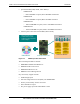
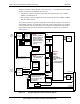
UNDP-1 Universal Notebook Data Platform User Guide Introduction A high-level hardware block diagram is shown in Figure 1-2. Two Hirose (U.FL-R-SMT) antenna connectors are provided for the following: 1. The primary connector supports transmission and reception by the active CDMA, UMTS, or GSM transceiver. 2. The secondary connector supports diversity reception by the active CDMA or UMTS link plus GPS reception.
UNDP-1 Universal Notebook Data Platform User Guide Introduction The primary antenna is connected to its RF front-end circuits (a switch module, CDMA and UMTS duplexers, etc). In the transmit direction, these front-end circuits are driven by the transmit output chains: two chains support GSM low and high bands (GSM850 + GSM900 and GSM1800 + GSM1900); three chains support CDMA (Cell + PCS) and UMTS (Cell + PCS + IMT) operation.
UNDP-1 Universal Notebook Data Platform User Guide 1.3 Introduction Terms and acronyms Table 1-3 defines the terms and acronyms used throughout this document.
UNDP-1 Universal Notebook Data Platform User Guide Table 1-3 Introduction Terms and Acronyms (continued) Term Definition TXCO Temperature-compensated Crystal Oscillator UICC Universal Integrated Circuit Card ULPI USB transceiver macrocell interface + low pin interface UMTS Universal Mobile Telecommunications System UNDP, UNDP-1 Universal Notebook Data Platform, -1 refers to a particular Qualcomm product USB Universal Serial Bus USIM Universal Subscriber Identity Module VCTCXO Voltage Co
2 External Connections The UNDP-1 add-in card is compatible with the PCI Express Mini Card 52-pin card edge type connector. The PCI Express Mini Card connector pin assignments are listed in Table 2-1; pins used by the UNDP-1 platform are highlighted in PINK BOLD font. Table 2-1 PCI Express Mini Card connector pin assignments System connector interface Pin # Name Pin # Name 51 N/C 52 +3.3 V 49 N/C 50 GND 47 N/C 48 N/C (+1.5 V) 45 N/C 46 N/C 43 GND 44 N/C 41 +3.
UNDP-1 Universal Notebook Data Platform User Guide External Connections The UNDP-1 platform also provides two RF connectors as antenna ports. Hirose model number U.FL-R-SMT should be used to mate with each port. See Section 1.2 for implementation and interconnection guidelines. The final set of connections available are the board-level pads available as a JTAG interface. The EDGE card connector and RF connectors are highlighted in Figure 2-1.
3 DC Power and UNDP Operating Modes 3.1 DC power source The host computer provides the UNDP-1 power source via the 52-pin card edge connector (Figure 3-1). A nominal supply voltage of 3.3 V is expected, as defined in the PCI Express Mini Card Electromechanical Specification, Revision 1.1. UNDP-1 voltage and current specifications are provided in the Universal Notebook Data Platform Device Specification (80-VF329-1).
UNDP-1 Universal Notebook Data Platform User Guide 3.2 DC Power and UNDP Operating Modes DC power states Based on applied DC power and control signals from the host computer, the UNDP-1 platform is set to one of four DC power states, as shown in Table 3-1. Table 3-1 UNDP-1 DC power states 1 State Description Disconnected DC power is not applied to the UNDP-1 platform. Off DC power is applied to the UNDP-1 platform, but the platform is disabled via the W_DISABLE_N control signal.
UNDP-1 Universal Notebook Data Platform User Guide 3.4 DC Power and UNDP Operating Modes Electrostatic discharge protection Electrostatic discharge (ESD) occurs naturally in laboratory and factory environments. An established high-voltage potential is always at risk of discharging to a lower potential. If this discharge path is through a semiconductor device, destructive damage may result. ESD countermeasures and handling methods must be developed and used to control the UNDP-1 platform’s environment.
4 RF Integration 4.1 RF operating frequencies The UNDP-1 RF operating frequencies are summarized in Table 4-1.
UNDP-1 Universal Notebook Data Platform User Guide RF Integration Three additional points are worth highlighting: 4.3 ■ Use short 50-Ohm cables for host-to-UNDP RF interconnections to minimize loss. Losses between an antenna and the receiver degrades sensitivity; loss in the transmit path requires additional PA output power (more DC power consumption). ■ Use an appropriate tool for antenna cable connections; the Hirose U.FL connector removal tool is recommended.
UNDP-1 Universal Notebook Data Platform User Guide Figure 4-1 NOTE 80-VF329-3 Rev. A RF Integration UNDP shields (highlighted in pink) These UNDP shields must not be removed. 20 QUALCOMM Confidential and Proprietary MAY CONTAIN U.S.
UNDP-1 Universal Notebook Data Platform User Guide RF Integration The host PC is a hostile environment for RF transceivers, making the shields absolutely necessary. Potential interference sources include the following: ■ Noise or ripple on the DC power supply voltage input lines, including transients due to switching-mode power supplies or host operating mode changes.
5 Platform Communications The main communications port between the host computer and the UNDP-1 platform (Figure 5-1) is the high-speed USB interface. This two-wire interface enables software downloads of boot, modem, and applications images, allows UNDP-1 status communications, and provides the control link from the host computer to the UNDP-1 platform. An off-chip USB transceiver (the USB ULPI PHY) is used to coordinate USB communications between the MDM1000 IC and the host computer.
UNDP-1 Universal Notebook Data Platform User Guide Platform Communications An external RUIM/USIM is supported via the off-board UICC. The PM6653 IC provides the USIM power supply, thereby enabling support for both 1.8 V and 2.85 V UICCs. All digital signals are buffered and level-translated by the PM6653 IC as well, ensuring compatiblity between the external module and the MDM1000 IC.
6 Standards and Regulatory Compliance 6.1 Standards and certification The UNDP-1 platform conforms to the following standards and certification requirements: ■ ■ CDMA ❒ TIA/EIA IS-98E (cdma2000 1x) ❒ TIA/EIA IS-866 (1xEV-DO) UMTS (WCDMA) ❒ ■ GSM ❒ ■ ■ TS 45.005 FCC ❒ 47 CFR Part 1 - RF radiation exposure limits ❒ 47 CFR Part 2 - Equipment authorization ❒ 47 CFR Part 15 - Unintentional radiators ❒ 47 CFR Part 22 - Cellular ❒ 47 CFR Part 24 - PCS CE ❒ ❒ 80-VF329-3 Rev. A TS 25.
UNDP-1 Universal Notebook Data Platform User Guide – 6.2 6.2.1 EN 301 607-1 - GSM900/GSM1800 ■ CTIA/GCF/PTCRB ■ Safety ❒ Standards and Regulatory Compliance EN 50360/61 full carrier certification (carriers TBD) ■ Microsoft WHQL certification ■ RoHS compliance Regulatory information Safety warnings Do not operate the UNDP-1 platform in the following environments: 6.2.
UNDP-1 Universal Notebook Data Platform User Guide Standards and Regulatory Compliance 3. To comply with FCC/IC regulations limiting both maximum RF output power and human exposure to RF radiation, maximum antenna gain (including cable loss) must not exceed: ❒ Cellular band < 4 dBi ❒ PCS band < 4 dBi ❒ IMT band < TBD dBi 4. Independent UNDP-1 operation — the UNDP-1 platform must not be co-located or jointly operated with any other transmitter or antenna within the host device. 5.