
User's Manual Part 2

80-J7615-1 Rev. A MAY CONTAIN U.S. AND INTERNATIONAL EXPORT CONTROLLED INFORMATION 13-5
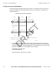
Installing the Auxiliary Sensor Wiring Schematic
10. Using blue or pink splices, connect the two gray wires coming from the AUX relay to the
two gray AUX_SENSOR wires on the TT210 system power/accessory cable (will be
near the TT210 system terminal). Refer to the wiring schematics in this document.
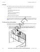
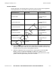
Wiring Schematic
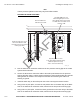
Schematic B
Pin 7
Pin 1
Inside the 7-way box
Tire
Pressure
Switch
Relay/Socket Assembly
86
87
87a
30
85
AUX - (Gray)
AUX + (Gray)
07AAA_72A
Tire Pressure Warning Light
Two-conductor wire to light
Black
White*
* NOTE: Tire Pressure Warning Light wire colors may vary.
White
Black
Two-conductor wire to tire pressure switch
GND (Black)
PWR (red)
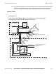
Wiring Schematic A
In this wiring configuration, the AUX relay is wired directly to the tire pressure warning light.
The 20-foot AUX sensor extension cable is used to connect the two.
PWR (red)
GND (Bl ack)
To TT210 system power/accessory
cable AUX_SENSOR +/-
(gray) inputs
20-foot Aux Sensor
Extension Cable
DRAFT