
User's Manual Part 2

Tire Pressure Sensor Kit Installation Installing the Auxiliary Sensor
13-4
MAY CONTAIN U.S. AND INTERNATIONAL EXPORT CONTROLLED INFORMATION 80-J7615-1 Rev. A
Note
The tire pressure light wire colors may vary from trailer to trailer.
CHANGE TO SHOW TT210 UNIT
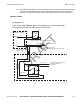
5. Run the AUX sensor extension cable from the tire pressure warning light to the TT210
system terminal location.
6. Secure the AUX sensor extension cable to the trailer post between the tire pressure
warning light bay and the TT210 system terminal bay using supplied cable ties and self-
drilling screws as needed. This will prevent vibration from severing the cable and
shorting to ground.
7. Install the AUX relay on the trailer post next to the TT210 system mount location.
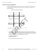
8. Using a blue or pink splice, connect the red positive wire on the AUX relay to the black
wire on the AUX sensor extension cable, routed from the tire pressure warning light.
9. Using a blue or pink splice, connect the black ground wire on the AUX relay to the white
wire on the AUX sensor extension cable, routed from the tire pressure warning light.
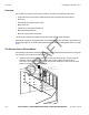
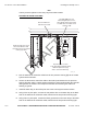
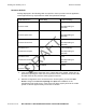
04AAA_140C
Gray AUX_Sensor +/ - w ires
on the TT210 System Power/Accessory
Cable butt-spliced to the gray
AUX +/ - wires on the AUX relay.
Red PWR (power) wire and
black GND (ground) wire on the
AUX relay butt-spliced to the white
and black wires on the AUX sensor
extension cable.
AUX sensor extension
cable-tied to the trailer.
Black and white wires on the
AUX sensor extension cable
butt-spliced to the tire pressure
warning light wires.
DRAFT