
User's Manual Part 2

80-J7615-1 Rev. A MAY CONTAIN U.S. AND INTERNATIONAL EXPORT CONTROLLED INFORMATION 13-3
Installing the Auxiliary Sensor Tire Pressure Sensor Kit Installation
2. Once the TT210 system diagnostic cable connector is located, activate Configuration
tool.
3. Perform a TT210 system verification to ensure the TT210 system is functioning properly
prior to installing the tire pressure sensor kit. (Refer to Chapter 14: Performing System
Verification.
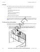
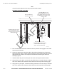
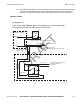
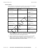
4. Butt splice the black and white wires of the 20-foot AUX sensor extension cable inline to
the tire pressure warning light wires. Refer to the following illustration and to Wiring
Schematic A on page 13-5 of this document.
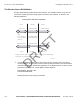
Use a multi-meter to determine polarity to make the following butt splice connections:
• Use a yellow splice supplied in the kit to connect the ground wire of the tire pressure
warning light to the white AUX sensor extension cable wire.
• Use a yellow splice supplied in the kit to connect the 12 VDC wire of the tire pressure
warning light to the black AUX sensor extension cable wire.
DRAFT