
User's Manual Part 2

Overview Installing the Auxiliary Sensor
13-2
MAY CONTAIN U.S. AND INTERNATIONAL EXPORT CONTROLLED INFORMATION 80-J7615-1 Rev. A
Overview
The TT210 tire pressure sensor kit (65-J7313-1) contains the following components:
• 20-foot AUX sensor extension cable assembly with convoluted protective tubing
•AUX relay
• Self-drilling hex washer-head screws
• Black cable ties
• Yellow inline, step-down butt splices
• Blue insulated butt splices
• Blue #10 ring terminal connectors
The AUX relay should be installed next to the TT210 system inside the trailer.
The chapter contains a wiring schematic of an installation with the AUX relay connected to the
tire pressure light via the 20-foot AUX extension cable. (Refer to Wiring Schematic A on page
13-5.)
Tire Pressure Sensor Kit Installation
The following instructions and wiring schematics provide details and procedures for wiring the
tire pressure sensor into the TT210 system.
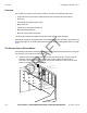
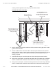
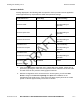
1. Inside the trailer at the trailer nose, remove the inner lining to gain access to the tire
pressure warning light installation site and the TT210 system diagnostic cable
connector. (It may also be necessary to remove the metal liner in the corner of some
trailers to access the tire pressure light.)
Tire pressure warning
Light Location
TT210 installation location
DRAFT