
User's Manual Part 2

Swing Door Sensor Installation Overview Installing the Swing Door Sensor
11-2
MAY CONTAIN U.S. AND INTERNATIONAL EXPORT CONTROLLED INFORMATION 80-J7615-1 Rev. A
Swing Door Sensor Installation Overview
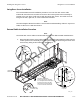
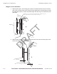
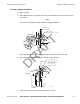
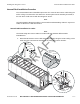
The swing door sensor kit contains the swing door sensor (with magnet and switch) and an
85-foot door sensor cable assembly. (The replacement swing door sensor kit comes without
the 85-foot cable assembly.)
The door sensor cable assembly can be routed two ways:
• Externally, under the trailer up to the TT210 system mount assembly (along the same
route as the factory wiring and/or brake lines).
• Internally, along the top of the trailer up to the TT210 system mount assembly.
For external cable installation, refer to External Cable Installation Procedure on page 11-3.
For internal cable installation, refer to Internal Cable Installation Procedure on page 11-9.
At the TT210 system mount assembly, the two door sensor cable wires are butt-spliced to the
YELLOW (DOOR-) and ORANGE (DOOR+) wires in the TT210 system power/accessory
cable assembly.
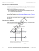
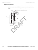
Swing Door Sensor Validation
A simple opened/closed magnetic switch detects when the state of a trailer door changes.
The interval is set up per the customer’s request and state change reports are sent to the
customer, as shown in the following illustration.
Closing Closed
Time Zero
Validation Time Validated
Set at NMC or Host
Default 20 minutes
Open
Open
ClosedOpening
Simple open and closed switch that detects a changed state immediately
and reports as configured by the customer.
TT210 System Door Sensor Validation
05AAA_025A
Time Zero
Validated Validation Time
DRAFT