1 Installing the Swing Door Sensor Introduction This chapter provides guidelines and instructions for installing the TT210 system trailer swing door sensor. AF T Topics in this chapter include: Swing Door Sensor Installation Overview . . . . . . . . . . . . . . . . . . . . . . . . . . . . . . . Swing Door Sensor Validation . . . . . . . . . . . . . . . . . . . . . . . . . . . . . . . . . . . . . . . . Swing Door Sensor Installation . . . . . . . . . . . . . . . . . . . . . . . . . . . . . . . . . . . .
Swing Door Sensor Installation Overview Installing the Swing Door Sensor Swing Door Sensor Installation Overview The swing door sensor kit contains the swing door sensor (with magnet and switch) and an 85-foot door sensor cable assembly. (The replacement swing door sensor kit comes without the 85-foot cable assembly.) The door sensor cable assembly can be routed two ways: • Externally, under the trailer up to the TT210 system mount assembly (along the same route as the factory wiring and/or brake lines).
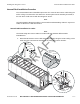
Installing the Swing Door Sensor Swing Door Sensor Installation Swing Door Sensor Installation The recommended external installation procedure is to route the door sensor cable underneath the trailer from the trailer nose where the TT210 system mount assembly is located, to the rear where it will connect with the swing door sensor. The cable can route along the left side, right side, or center underneath the trailer. Note The entire length of the 85-foot cable is covered with convoluted tubing.
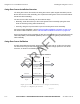
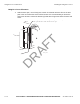
Swing Door Sensor Placement Installing the Swing Door Sensor Swing Door Sensor Placement 1. With the door open, use a felt-tip pen to mark a horizontal reference line on the door post in the area where the sensor will be located. Qualcomm recommends you locate the swing door sensor 2" above the bottom right side door hinge area where the door seal ends. Mark the post 2" above the lower right door hinge with the door open on the panel that faces inside when the door is open. AF T approx. 2.
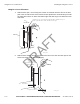
Installing the Swing Door Sensor Swing Door Magnet Installation Swing Door Magnet Installation 1. Open the door. 2. Drill a 3/8" diameter x 7/8" deep hole along the horizontal line at the centerline of the door width. Note The 3/8" hole diameter is critical for proper magnet installation. Centerline of the door width AF T Drill 3/8"hole approximately 7/8" deep Door Seal 05AAA_235 Apply a generous amount of adhesive/sealant into the 3/8" hole in the door. 4.
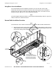
Swing Door Sensor Installation Installing the Swing Door Sensor Swing Door Sensor Installation 1. Remove the taillight assembly from the trailer’s passenger side. Most taillight assemblies are held into place by a large rubber grommet. 2. Using a center punch, mark a spot on the door post to line up with the horizontal line and the middle of the door when the door is closed. This is where the switch will be located. 3. Drill a 1/2" hole at this point in the door post.
Installing the Swing Door Sensor 5. Testing the Swing Door Sensor Apply adhesive/sealant to the sensor and inside the hole in the door post. AF T Adhesive/Sealant 05AAA_229 Press the sensor all the way into the 1/2" hole until it is fully seated. 7. Wipe off any excess adhesive/sealant. R 6. Testing the Swing Door Sensor 2. Attach an ohmmeter to the sensor wires. D 1. Close the door and check the ohmmeter for proper swing door sensor operation.
Swing Door Sensor Installation Verification Installing the Swing Door Sensor Swing Door Sensor Installation Verification 1. At the back of the trailer, butt splice the white sensor wires to the orange and yellow cable wires. Add additional strain relief by following the procedure on page 3-7. Slide convoluted tubing onto sensor wires, making sure to also cover the butt splices. Store excess wire behind the taillight assembly. 2. Replace the taillight assembly.
Installing the Swing Door Sensor Internal Cable Installation Procedure Internal Cable Installation Procedure The recommended internal installation procedure is to route the door sensor cable along the trailer “ceiling” from the trailer nose where the TT210 system mount assembly is located, to the rear where it will connect with the swing door sensor. Note The entire length of the 85-foot cable is covered with convoluted tubing. If there is any excess cable, cut the excess cable and discard.
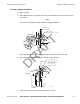
Swing Door Sensor Placement Installing the Swing Door Sensor Swing Door Sensor Placement 1. With the door open, use a felt-tip pen to mark a horizontal reference line on the door post in the area where the sensor will be located. It is recommended you locate the swing door sensor 2" above the bottom right side door hinge area where the door seal ends. Mark the post 2" above the lower right door hinge with the door open on the panel that faces inside when the door is open. AF T approx. 2.
Installing the Swing Door Sensor 2. Swing Door Sensor Placement With the door closed, mark a horizontal reference line on the door and door post so the sensor and magnet can be easily aligned. Door Post AF T Trace the edge of the door onto the door post. Approximately an 18" high vertical line. Cargo door closed D R 05AAA_236B 80-J7615-1 Rev. A MAY CONTAIN U.S.
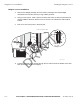
Swing Door Magnet Installation Installing the Swing Door Sensor Swing Door Magnet Installation 1. Open the door. 2. Drill a 3/8" diameter x 7/8" deep hole along the horizontal line at the centerline of the door width. Note The 3/8" hole diameter is critical for proper magnet installation. Centerline of the door width AF T Drill 3/8"hole approximately 7/8" deep Door Seal 05AAA_235 Apply a generous amount of adhesive/sealant into the 3/8" hole in the door. 4.
Installing the Swing Door Sensor Swing Door Sensor Installation Swing Door Sensor Installation 1. Remove the taillight assembly from the trailer’s passenger side. Most taillight assemblies are held into place by a large rubber grommet. 2. Using a center punch, mark a spot on the door post to line up with the horizontal line and the middle of the door when the door is closed. This is where the switch will be located. 3. Drill a 1/2" hole at this point in the door post.
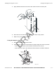
Testing the Swing Door Sensor 5. Installing the Swing Door Sensor Apply adhesive/sealant to the sensor and inside the hole in the door post. AF T Adhesive/Sealant 05AAA_229 6. Press the sensor all the way into the 1/2" hole until it is fully seated. 7. Wipe off any excess adhesive/sealant. R Testing the Swing Door Sensor 1. Attach an ohmmeter to the sensor wires. 2. Close the door and check the ohmmeter for proper swing door sensor operation.
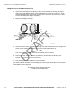
Installing the Swing Door Sensor Swing Door Sensor Installation Verification Swing Door Sensor Installation Verification 1. At the back of the trailer, butt splice the white sensor wires to the orange and yellow cable wires. Add additional strain relief by following the procedure on page 3-7. Slide convoluted tubing onto sensor wires, making sure to also cover the butt splices. Store excess wire behind the taillight assembly. 2. Replace the taillight assembly. Yellow Orange 3.
Installing the Swing Door Sensor D R AF T Swing Door Sensor Installation Verification 11-16 MAY CONTAIN U.S. AND INTERNATIONAL EXPORT CONTROLLED INFORMATION 80-J7615-1 Rev.
12 Installing the Roll Door Sensor Introduction This chapter provides guidelines and instructions for installing the TT210 system trailer roll door sensor. AF T Topics in this chapter include: Roll Door Sensor Installation Overview . . . . . . . . . . . . . . . . . . . . . . . . . . . . . . . . . Roll Door Sensor Validation . . . . . . . . . . . . . . . . . . . . . . . . . . . . . . . . . . . . . . . . . . Roll Door Sensor Installation . . . . . . . . . . . . . . . . . . . . . . . . . . . . . . . . . . .
Roll Door Sensor Installation Overview Installing the Roll Door Sensor Roll Door Sensor Installation Overview The roll door sensor kit contains the rear door switch with attached 3-foot cable assembly, a magnet, and an 85-foot door sensor cable assembly. (The replacement roll door sensor kit comes without the 85-foot cable assembly.
Installing the Roll Door Sensor Roll Door Sensor Installation Roll Door Sensor Installation The recommended external installation procedure is to route the door sensor cable underneath the trailer from the trailer nose where the TT210 system mount assembly is located, to the rear where it will connect with the roll door sensor. The cable can route along the left side, right side, or center underneath the trailer. Note The entire length of the 85-foot cable is covered with convoluted tubing.
Roll Door Sensor Installation Installing the Roll Door Sensor Roll Door Sensor Installation 1. With the trailer roll door closed, use a felt-tip pen to draw a line along the inside of the passenger side of the door, close to door jamb. 2. Open the trailer roll door and position the roll door sensor switch as close as possible to the door jamb to avoid damage to the door sensor cable when loading the trailer. Take into consideration that the door sensor cable has a bend radius of two inches.
Installing the Roll Door Sensor Position the roll door sensor switch and mark the holes for the roll door sensor switch using a 3/16" drill bit. AF T 4. Roll Door Sensor Installation 06AAA_211a 5. Remove the taillight assembly from the trailer’s passenger side. Most taillight assemblies are held into place by a large rubber grommet. D R Rubber Seal Retainer Taillight Assembly 6. 80-J7615-1 Rev.
Roll Door Sensor Installation 7. Installing the Roll Door Sensor Drill a 1/2” hole at this point in the trailer floor. AF T Drill a 1/2" hole, approximately 5/8" minimum in from marked reference line and as close into the corner as possible. Take care to drill straight down. 5/8" 06AAA_217 Feed the sensor cable leads through the 1/2” hole and out the bottom of the trailer floor into the area behind the taillight. D R 8. Feed the armored cable down into the 1/2" drilled hole.
Installing the Roll Door Sensor 9. Position the roll door sensor on the trailer floor to be aligned with the vertical reference line you marked. Secure the roll door sensor in place with the self-drilling screws. Pilot holes may be required. AF T 10. Roll Door Sensor Installation D R Use self-drilling screws to anchor the sensor. 2" Cable Radius Self-drilling Screws 80-J7615-1 Rev. A 06AAA_211 MAY CONTAIN U.S.
Roll Door Magnet Installation Installing the Roll Door Sensor Roll Door Magnet Installation Note The bottom of the trailer door may have a metal strip. Placement of the magnet may pitch the angle of the magnet forward over the roll door sensor switch. As long as the magnet is positioned within one inch of the top of the roll door sensor switch, the roll door sensor will operate properly.
Installing the Roll Door Sensor Roll Door Magnet Installation AF T Mark the horizontal location for mounting the magnet. 06AAA_215 0.75 Open and secure the door part way. 3. Position the magnet within the reference lines. 4. Secure the magnet using the self-drilling screws. D R 2. With the roll-up door open, install the magnet with the self-drilling mounting screws. 06AAA_213 80-J7615-1 Rev. A MAY CONTAIN U.S.
Roll Door Magnet Installation 5. Installing the Roll Door Sensor Close the trailer door and ensure the sensor switch and magnet are aligned. Ensure also there is some clearance between the sensor switch and the magnet. Magnet 06AAA_212 AF T Carefully close the roll-up door, and check to be sure there is some clearance between the sensor and the magnet. Roll-up Door 0.75 " 2.0" min R . D SENSOR 06AAA_207 12-10 MAY CONTAIN U.S. AND INTERNATIONAL EXPORT CONTROLLED INFORMATION 80-J7615-1 Rev.
Installing the Roll Door Sensor Testing the Roll Door Sensor Testing the Roll Door Sensor 1. Attach an ohmmeter to the sensor wires. 2. Close the door and check the ohmmeter for proper roll door sensor operation. • When the door is closed, the ohmmeter should measure 0 ohms. D R AF T • When the door is open, the ohmmeter should measure infinite resistance.
Testing the Roll Door Sensor Installing the Roll Door Sensor Magnet AF T Sensor D R From Sensor From Terminal FLUKE 77 III 0 RANGE MULTIMETER 10 20 30 HOLD mV V A OFF A 300 mA 10 A V COM Doors Open 12-12 06AAA_216 MAY CONTAIN U.S. AND INTERNATIONAL EXPORT CONTROLLED INFORMATION 80-J7615-1 Rev.
Installing the Roll Door Sensor Roll Door Sensor Installation Verification Roll Door Sensor Installation Verification 1. At the back of the trailer, butt splice the white sensor wires to the orange and yellow cable wires. Add additional strain relief by following the procedure on page 3-7. Yellow Orange AF T When the test is completed and the circuit tests O.K. , splice the sensor wires to the terminal wires. 05AAA_246A Note The sensor is a simple switch device; polarity does not matter. 2.
Roll Door Sensor Installation Verification 4. Installing the Roll Door Sensor At the front of the trailer, butt splice the orange and yellow cable wires to the orange and yellow TT210 system door sensor wires at the TT210 system terminal. To TT210 System Mount Assembly Orange Yellow Orange AF T Yellow To Door Sensor 06AAA_222 Note The sensor is a simple switch device; polarity does not matter.
Installing the Roll Door Sensor Roll Door Sensor Installation Verification If you have technical questions about installing the TT210 system roll door sensor, please contact QES Customer Support: D R AF T In the United States, call 800-541-7490; in Canada, call 800-863-9191. 80-J7615-1 Rev. A MAY CONTAIN U.S.
Installing the Roll Door Sensor D R AF T Roll Door Sensor Installation Verification 12-16 MAY CONTAIN U.S. AND INTERNATIONAL EXPORT CONTROLLED INFORMATION 80-J7615-1 Rev.
13 Installing the Auxiliary Sensor Introduction AF T The TT210 auxiliary sensor wires are available on the TT210 power/accessory cable assembly. This sensor option allows customers to use a third-party sensor with the TT210 system. The TT210 AUX sensor input is designed to detect digital (on/off switch) signals only. The TT210 system can be configured to generate alerts when an input transitions from high to low or from low to high. Topics in this chapter include: R Overview . . . . . . . . . . . . . .
Overview Installing the Auxiliary Sensor Overview The TT210 tire pressure sensor kit (65-J7313-1) contains the following components: • 20-foot AUX sensor extension cable assembly with convoluted protective tubing • AUX relay • Self-drilling hex washer-head screws • Black cable ties • Yellow inline, step-down butt splices • Blue insulated butt splices • Blue #10 ring terminal connectors The AUX relay should be installed next to the TT210 system inside the trailer.
Installing the Auxiliary Sensor Tire Pressure Sensor Kit Installation 2. Once the TT210 system diagnostic cable connector is located, activate Configuration tool. 3. Perform a TT210 system verification to ensure the TT210 system is functioning properly prior to installing the tire pressure sensor kit. (Refer to Chapter 14: Performing System Verification. 4. Butt splice the black and white wires of the 20-foot AUX sensor extension cable inline to the tire pressure warning light wires.
Tire Pressure Sensor Kit Installation Installing the Auxiliary Sensor Note The tire pressure light wire colors may vary from trailer to trailer. CHANGE TO SHOW TT210 UNIT 13-4 D R Black and white wires on the AUX sensor xtension e cable butt-spliced to the tire pressure warning light wires. AF T AUX sensor xtension e cable-tied to the trailer. Red PWR (po wer) wire and black GND (ground) wire on the AUX relay butt-spliced to the white and black wires on the A UX sensor extension cable.
Installing the Auxiliary Sensor Wiring Schematic Using blue or pink splices, connect the two gray wires coming from the AUX relay to the two gray AUX_SENSOR wires on the TT210 system power/accessory cable (will be near the TT210 system terminal). Refer to the wiring schematics in this document. 10. Wiring Schematic Schematic B Wiring Sc hematic A In this wiring configuration, the AUX relay is wired directl y to the tire pressure warning light.
Tire Pressure Sensor Kit Validation Installing the Auxiliary Sensor Tire Pressure Sensor Kit Validation A simple opened/closed switch detects tire pressure. The validation time is set up per the customer’s request and state change reports are sent to the customer, as shown in the following illustration. TT210 System AUX Sensor Validation Closing Open Validation Time Note: FST s/w forces 5-second check interval.
Installing the Auxiliary Sensor Parameter Defaults Parameter Defaults Settings displayed in the following table are specific to the tire pressure sensor application. Other applications may require different initial and operational settings.
Installing the Auxiliary Sensor D R AF T Parameter Defaults 13-8 MAY CONTAIN U.S. AND INTERNATIONAL EXPORT CONTROLLED INFORMATION 80-J7615-1 Rev.
14 Performing System Verification Introduction to System Verification This chapter describes the TT210 system verification process and basic diagnostic procedures. AF T Topics in this chapter include: D R What Is TT210 System Verification? . . . . . . . . . . . . . . . . . . . . . . . . . . . . . . . . . . . 14-2 TT210 System Verification . . . . . . . . . . . . . . . . . . . . . . . . . . . . . . . . . . . . . . . . . . . 14-2 Diagnostic Flowchart—TT210 System Verification . . . . . . . . . . . . . .
What Is TT210 System Verification? Performing System Verification What Is TT210 System Verification? The TT210 system verification is a functional system check that should be performed after installation of the TT210 system and after service to verify the TT210 system is operating properly. The chapters following this System Verification chapter provide the diagnostics steps necessary to resolve any problem that appears during the system verification.
Performing System Verification Diagnostic Flowchart—TT210 System Verification Diagnostic Flowchart—TT210 System Verification Step 1 Ensure all electrical connections are made. Yes Step 11 Step 2 Step 3 Yes Disconnect 7-way and reefer power if connected. Step 21 Start the Config Tool software. Step 12 Wake the unit either by using the keyfob or applying 7-way power. You have 1 minute to make Bluetooth connection. Click the Connect button on your laptop.
TT210 System Verification Procedure Performing System Verification TT210 System Verification Procedure 1. Ensure that the following electrical connections are made: External power should not be applied to the TT210 system terminal until except to start Bluetooth. • The blue (POWER) and white (GROUND) wires from the TT210 system power/ accessory cable are connected to the trailer’s 7-way. • RF connections/antenna connections.
Performing System Verification If this is a new installation, the Configuration tool software will prompt you to enter the trailer ID. Qualcomm recommends that the trailer ID be set at this time. (This process associates the trailer ID with the TT210 system terminal’s ID in the customer’s account.) AF T 5. TT210 System Verification Procedure For detailed information regarding entering the trailer ID, refer to the TT200/TT210 Configuration Tool Quick Reference, 80-J7595-1.
Performing System Verification Cargo Sensor verification. If a cargo sensor is installed on the trailer, verify it is functioning correctly by toggling the current state. D 7. R AF T TT210 System Verification Procedure NOTE: How to Toggle the Cargo Sensor If the trailer is empty, block the cargo sensor by holding a piece of cardboard approximately 6 inches from the cargo sensor. Confirm the cargo sensor state changes from Empty to Loading or Loaded.
Performing System Verification 8. TT210 System Verification Procedure Door Sensor verification. If a door sensor is installed on the trailer, verify it is functioning correctly by toggling the current state. NOTE: How to Toggle the Door Sensor If the trailer door is closed, open it. Confirm the door sensor state changes from Closed to Opening or Open. If the trailer door is open, close it. Confirm the door sensor state changes from Open to Closing or Closed.
TT210 System Verification Procedure Performing System Verification 7-way receptacle + _ BATTERY Remove external power from the 7-way receptacle. 13. AF T 04AAA_127E Does the Battery show a voltage rather than charging? • If NO, cover the solar panel to turn off the charging circuit. 14. Is the Battery voltage 3.7 volts or higher? R NOTE: This verification must be done without external power applied to the TT210 system terminal.
Performing System Verification TT210 System Verification Procedure 7-way receptacle + _ BATTERY 18. 04AAA_127D_tt210 AF T The TT210 system external power test cable can be used to apply external power. Does the 7W field display a voltage of greater than 9 VDC? If YES, go to step 19. If NO, go to Chapter 24: TT210 System Diagnostics: External 7-way Power. 19. If this installation does not include reefer power, go to step 22. 20. Turn on reefer.
TT210 System Verification Procedure Performing System Verification To verify the trailer ID using the 7-way diagnostic tool go to Getting the TT210 System Terminal ID Using the 7-way Diagnostic Tool on page 14-11. To verify the trailer ID for an MCP unit go to////. ??? • If YES, system verification is complete. D R AF T • If NO and you are using the 7-way diagnostic tool, go to Chapter 28: TT210 System Diagnostics: Power Bus Modem. 14-10 MAY CONTAIN U.S.
Performing System Verification Getting the TT210 System Terminal ID Using the 7-way Diagnostic Tool Getting the TT210 System Terminal ID Using the 7-way Diagnostic Tool Complete the following procedure to launch the 7-way diagnostic tool software on your handheld Palm device. To Launch the 7-way Diagnostic Tool Software Connect the 7-way tool to the handheld device via the handheld’s serial cable. 2.
To Launch the 7-way Diagnostic Tool Software Performing System Verification AF T If the 7-way diagnostic tool software detects a problem while connecting to the terminal, the software attempts to connect to the terminal for approximately two minutes before you are given additional information regarding the problem: The following are situations that can occur with the TT210 system terminal that can cause the connection process to fail: • Discharged 7-way tool battery • Faulty cable connections • Unrespon
Performing System Verification 7-Way Tool Health Screen Information 7-Way Tool Health Screen Information AF T The 7-Way Tool Health screen lists the latest values detected from the terminal, including a terminal’s registration status. If multiple terminals are detected, you can change the currently viewed terminal by selecting a different terminal. To select a different terminal, tap the dropdown arrow next to the terminal number (e.g., 120000001) near the upper-right corner of the screen.
Diagnostic Values Performing System Verification Door Sensor Status The trailer/container swing door sensor status shows as: NOT INSTALLED, OPEN/OPENING or CLOSED/CLOSING. Auxiliary Sensor Status If third-party accessories are installed, the auxiliary sensor input status shows as: NOT INSTALLED, OPEN/OPENING or CLOSED/CLOSING. GPS The GPS status shows as: 2D FIX (good), 3D FIX (best), or NO FIX. Antenna Status AF T The Ant status shows as: OK.
Performing System Verification Tethered Asset Management Service Overview Tethered Asset Management Service Overview The tethered asset management service is an option that allows dispatch to monitor trailer connections and disconnections. Connects and disconnects are detected by the mobile communications terminal and passed on to dispatch via the satellite link with the date, time, and location. Firmware Requirements The mobile communications terminal firmware version must be 15.
Trailer Connection/Disconnection 4. Performing System Verification Press until the TrailerTRACS ID screen is displayed. If “Hit C to Connect” (see illustration below) is displayed on the screen, Auto Connect is not enabled. Call the QES Customer Support to enable Auto Connect. In the United States, call 800-541-7490; in Canada, call 800-863-9191. Have the mobile communications terminal serial number (unit address) available when you call.
Performing System Verification 3. Tethered Asset Management Service Diagnostic Screen Wait up to five minutes for disconnect message. A disconnect message is sent when the tractor’s ignition is on and there has been no signal from the tethered transmitter for a preset time period. This will usually occur within five minutes. WARNING: A TRAILER HAS DISCONNECTED (ANY FUNCTION KEY EXITS.
Getting the TT210 System Terminal ID (EDU) Performing System Verification Getting the TT210 System Terminal ID (EDU) This section provides information on system verification for single trailer connections and disconnections. Enable the Tethered Asset Management Service and Auto Connect Note If tethered asset management service screens are not available, then the tethered asset management service option is not enabled.
Performing System Verification 4. Trailer Connection/Disconnection Press until the TrailerTRACS ID screen is displayed. If “Hit ‘C’ to connect” (see the following illustration) appears this means Auto Connect is not enabled. Call the QES Customer Support to enable Auto Connect. In the United States, call 800-541-7490; in Canada, call 800-863-9191. Have the mobile communications terminal serial number (unit address) available when you call.
Trailer Connection/Disconnection Performing System Verification After the trailer is connected and the TrailerTRACS system transmitter sends its ID to the mobile communications terminal, the trailer ID is updated on the EDU as shown in the following screen. USE ↑ ((↓) TO MOVE TO PREV(NEXT)SCREEN TRAILERTRACS ID#'s CONNECTED: 1234 READ PREV Disconnection REPLY CREATE MSG SEND AF T READ NEXT 1. Remove 7-way pigtail. 2. Leave ignition on. 3. Wait up to five minutes for disconnect message.
Tethered Asset Management Service Diagnostic Screen Performing System Verification Tethered Asset Management Service Diagnostic Screen From the previous tethered asset management service ID screen, press the D key to view the tethered asset management service Diagnostic screen. This screen may be helpful when performing diagnostics. The following illustration shows a tethered asset management service Diagnostic screen without a connected trailer.
Getting the TT210 System Terminal ID (MVPc) Performing System Verification Getting the TT210 System Terminal ID (MVPc) This section provides information on system verification for single trailer connections and disconnections. Enable Tethered Asset Management Service and Auto Connect Note If tethered asset management service screens are not available, then the tethered asset management service option is not enabled.
Performing System Verification Trailer Connection/Disconnection If a trailer is not currently connected, the status is None Connected, as shown in the following figure. Disconnection 2. 3. Remove 7-way pigtail. D 1. R AF T After the trailer is connected and the TrailerTRACS transmitter sends its ID to the mobile communications terminal, the trailer ID is updated on the MVPc as shown in the following screen. Leave ignition on. Wait up to five minutes for disconnect message.
Tethered Asset Management Service Diagnostic Screen Performing System Verification Tethered Asset Management Service Diagnostic Screen AF T From the previous tethered asset management service ID screen, press the D key to view the tethered asset management service Diagnostic screen. This screen may be helpful when performing diagnostics. The following illustration shows a tethered asset management service Diagnostic screen without a connected trailer.
Performing System Verification Getting the TT210 System Terminal ID MCP (100) Getting the TT210 System Terminal ID MCP (100) This section provides information on system verification for single trailer connections and disconnections on the MCP100. Note If the screen does not appear, call your company to have Trailer Tracks asset management enabled. Have the MCP200 number ready when you call. The unit will need to be added to the appropriate operational profile.
Trailer Connection/Disconnection 5. Performing System Verification Is a refrigeration unit being monitored? Note R AF T If a refrigeration unit is detected, a snowflake will appear above the transmitter ID box. • If yes, go to step 6. 6. D • If no, go to step 7. With the reefer turned on, check that the Refrigerator Stat # is incrementing on the Trailer Management screen. This number should increment approximately once a minute. • If it is incrementing, go to step 7. 14-26 MAY CONTAIN U.S.
Performing System Verification 7. Trailer Connection/Disconnection Disconnect the tractor from the trailer, leave the ignition ON, and wait for the disconnect message as shown at left. (Allow up to 10 minutes.) • When the disconnect message appears on the display screen, Trailer Tracks asset management system verification is complete. • If disconnect message does not appear (allow up to 10 minutes), call QES Customer Support: D R AF T US: 800-541-7490 Canada: 800-863-9191 80-J7615-1 Rev.
Getting the TT210 System Terminal ID MCP (110 and 200) Performing System Verification Getting the TT210 System Terminal ID MCP (110 and 200) This section provides information on system verification for single trailer connections and disconnections on the MCP. Note If the screen does not appear, call your company to have Trailer Tracks asset management enabled. Have the MCP110 or MCP200 number ready when you call. The unit will need to be added to the appropriate operational profile.
Performing System Verification 5. Trailer Connection/Disconnection Is a refrigeration unit being monitored? Note AF T If a refrigeration unit is detected, a snowflake will appear above the transmitter ID box. • If yes, go to step 6. • If no, go to step 7. 6. With the reefer turned on, check that the Refrigerator Stat # is incrementing on the Trailer Management screen. This number should increment approximately once a minute. D R • If it is incrementing, go to step 7. 7.
Ongoing Maintenance Performing System Verification Ongoing Maintenance AF T Qualcomm recommends that, when you perform preventive maintenance on the tractor and trailer, you perform the following checks on the tethered system. Maintaining the Tethered System on Tractors Do the following to ensure optimum system performance on the tractor: • Secure cables from movement. • Cover any exposed cables with convoluted tubing. • Inspect, clean, and apply dielectric grease to all 7-way connection points.
Performing System Verification Troubleshooting Troubleshooting Problem Solution Connection: Will not connect to tractor. 1. Is Auto Connect enabled? 2. Check 5-amp fuse on the mobile communications terminal TTRACS wire. Disconnection: System Verification Form 1. Disconnect tractor 7-way pigtail. 2. Turn key to the ON position (could take up to five minutes for the disconnect to occur). AF T Will not disconnect. On the following page is the TT210 System Verification Form.
System Verification Form Performing System Verification TT210 SYSTEM VERIFICATION FORM Installer(s): Date: Trailer Information Trailer ID: Customer: Make: Location: Model: Terminal ID: Year: System Verification Accessories/Options Installed Cargo Sensor: Door Sensor: Aux Sensor: Shows Loaded and Unloaded Shows Opened and Closed Shows Opened and Closed GPS Fix: Reefer Power On: Yes No Yes No Yes No TT210 System Mount (type): Solar: Other: Phone Signal Strength: Nu
Performing System Verification TT210 System Verification Checklist??? too many checklists???? TT210 System Verification Checklist??? too many checklists???? The following system verification checklist presents a quick and efficient way to proceed through the TT210 system verification process.
TT210 System Verification Checklist??? too many checklists???? Performing System Verification D R AF T 14-34 MAY CONTAIN U.S.AND INTERNATIONAL EXPORT CONTROLLED INFORMATION 80-J7615-1 Rev.