
User's Manual Part 1

80-J7615-1 Rev. A MAY CONTAIN U.S. AND INTERNATIONAL EXPORT CONTROLLED INFORMATION 8-11
Installing the TT210 Terminal on Reefers Making Power and Signal Connections for Carrier Units
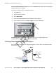
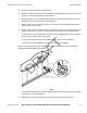
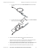
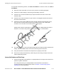
a. For newer model Carrier units, use cable # 45-J7856-6 with the 3-pin Packard
connector.
b. For older model Carrier units or units with Data Loggers, use cable # 45-J7854-6
with the 5-pin circular Deutsch connector.
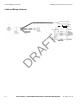
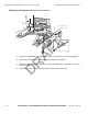
5. Connect the reefer power (ORN) wire with the SPK7 (switched power) wire.
Note
Reefer power must be connected to a circuit that only has voltage when the reefer is
turned on. For Carrier reefers, the wire labeled SPK7 is recommended.
6. Connect the ground (BLU) wire with the SPK23 or 24 wire. These are both ground wires
and are located in the same area as the reefer connector and the SPK7 wire.
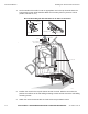
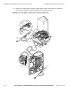
7. Verify that all mechanical and electrical components are properly connected.
07AAA_097
07AAA_102
DRAFT