
User's Manual Part 1

TT210 Power/Accessory Cable - Optional TT210 System Component Overview
2-6
MAY CONTAIN U.S. AND INTERNATIONAL EXPORT CONTROLLED INFORMATION 80-J7615-1 Rev. A
ALERT!
Immediately recharge the battery pack if it measures OCV < 3.90V. The terminal will go into
hibernate state when it reaches 3.60V.
When stored or not installed, Qualcomm recommends auditing the battery pack open circuit
voltage (OCV) every six months to ensure that it does not drop below 3.90V. If the storage
temperature is greater than 85° F, the audits should take place more frequently. Immediately
recharge the battery pack if it measures OCV < 3.90V. Batteries that sit for more than six
months must be recharged. You can use a battery charger or run external power to a TT210
unit for a couple of hours for a full charge.
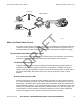
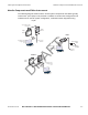
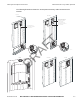
TT210 Power/Accessory Cable - Optional
The TT210 power/accessory cable connects the TT210 system terminal to the trailer’s 7-way
electrical system. The cable also interconnects any optional accessories to the TT210 system
terminal. The three optional accessories allow customers to optimize the system with a cargo
sensor, door sensor, and/or an auxiliary sensor. The blue wire is crimped to a fuse holder that
has a 3-amp, fast-acting ATM type automotive fuse and connects to pin 7 of the 7-way. The
white wire connects to pin 1 of the 7-way. The illustration shows the various cable assemblies.
10AAA_12
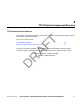
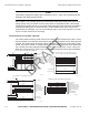
Dry Van Cable Assembly Wiring Diagram
BLU 16
WHT 16
BLU 20
WHT 20
BLU 20
WHT 20
BLK 20
BLK 20
GRN 20
YEL 20
BRN 20
RED 20
RED 20
BLK 20
GRA 20
ORN 20
P2
1
2
4
5
3
6
1
2
E
4
3
7
5
6
8
9
10
( EXT_PWR_IN)
(PWR_GND)
(REFFER_PWR_IN (NC ))
(SOLAR_PWR_IN (NC))
(CARGO_SENSOR_PWR)
(CARGO_SENSOR_TX)
(CARGO_SENSOR_RX)
(GND)
(AUX_SENSOR)
(DOOR_SENSOR)
10AAA_14
P11P1
B8
A8
B1
A4
B4
B3
A3
A5
A6
A7
BLU 16
WHT 16
BLK 20
GRA 20
ORN 20
GRN 20
YEL 20
BRN 20
RED 20
1
2
3
7
5
6
8
4
9
10
(AUX_SENSOR)
(DOOR_SENSOR)
(EXT_PWR_IN)
(PWR_GND)
(SOLAR_PWR_IN )
(CARGO_SENSOR_TX)
(CARGO_SENSOR_RX)
(GND)
(CARGO_SENSOR_PWR)
(N/C)
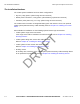
TT210 Retrofit Cable Assembly Wiring Diagram
(for use with existing TT200 installations)
BLU 16
WHT 16
ORN 20
GRA 20
BLU 20
WHT 20
BLK 20
GRN 20
YEL 20
BRN 20
RED 20
P2
EI
1
2
4
3
7
5
6
8
9
10
(PWR_GND)
(REFFER_PWR_IN)
(SOLAR_PWR_IN )
(CARGO_SENSOR_TX)
(CARGO_SENSOR_RX)
(GND)
(AUX_SENSOR)
(DOOR_SENSOR)
Reefer Cable Assembly Wiring Diagram
( EXT_PWR_IN)
(CARGO_SENSOR_PWR)
BLK 20
BLK 20
3
4
2
1
5
6
3X (16)
10AAA_13
10AAA_15
BLU 20
WHT 20
BLK 20
GRN 20
YEL 20
BRN 20
RED 20
GRA 20
ORN 20
( EXT_PWR_IN)
(PWR_GND)
(REFFER_PWR_IN (NC
))
(SOLAR_PWR_IN (NC))
(CARGO_SENSOR_PWR
)
(CARGO_SENSOR_TX)
(CARGO_SENSOR_RX)
(GND)
(AUX_SENSOR)
(DOOR_SENSOR)
1
2
4
3
7
5
6
8
9
10
1
2
4
5
3
6
P1
P2
Cargo Only Cable Assembly Wiring Diagram
DRAFT