
User's Manual

80-J7615-1 Rev. A MAY CONTAIN U.S. AND INTERNATIONAL EXPORT CONTROLLED INFORMATION 15-5
Performing System Verification TT210 System Verification Procedure
TT210 System Verification Procedure
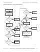
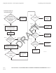
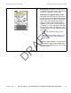
The steps in this procedure match the steps on the
preceding system verification flowchart. The steps
are not always sequential—you may be instructed to
skip steps.
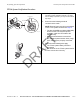
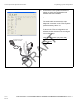
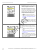
1. Ensure that the following electrical
connections are made:
NOTE: External power should not be applied
to the TT210 system terminal until step 13.
• The blue (POWER) and white (GROUND)
wires from the TT210 system power/
accessory cable are connected to the
trailer’s 7-way.
• RF connections/antenna connections.
• Any installed optional sensor wires (cargo,
door, and AUX) are properly connected.
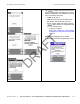
Ensure that the following also apply:
• The TT210 system battery should be
connected.
• The antenna for the TT210 system should
have a clear view of the sky.
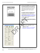
05AAA_217D
GRN
RED
YEL
BLK
BLU
BRN
White (GND)
Pin 1
Blue (PWR) Pin 7
7.5 amp Fuse
ol
03AAA_264a
DRAFT