
User's Manual
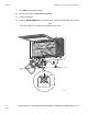

Making Power and Signal Connections for Carrier Units Installing the TT210 Terminal on Reefers
8-10
MAY CONTAIN U.S. AND INTERNATIONAL EXPORT CONTROLLED INFORMATION80-J7615-1
Rev. A
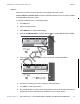
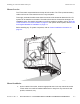
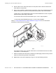
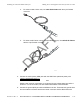
Making Power and Signal Connections for Carrier Units
1. Route the reefer/power data cable so it is secured to prevent it from being damaged.
2. Connect the TT210 battery to the mating TT210 terminal connector.
3. Connect to the TT210 unit with the 6-pin square Deutsch connector on the reefer
interface cable.
4. Connect the other end of the reefer interface cable to the reefer unit.
SP12SP12
SP12SP12
SP12SP12
SP12SP12
SP12SP12
SP12SP12
SP12
SP12
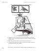
SETPOINT
BOX TEMPERATURE
SELECTSELE CT
START-S
TOP/START-STO P/
CONT INUOUS
CONT INUOU S
MANUAL
MAN UAL
DEFR OST
DEFR OST
ALAR M LIST
ALAR M LIS T
!
=
HEAT COOL
DEFROST
ALARM
START- STOP
CONTINUOUS
START / RUN
o
OFF
08AAA_034A
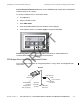
Data Cable
45-J7856-6
NOTE: This is the only
3-pin connector located
in the area.
DRAFT