
User's Manual

80-J7615-1 Rev. A MAY CONTAIN U.S. AND INTERNATIONAL EXPORT CONTROLLED INFORMATION 2-7
TT210 System Component Overview TT210 Power/Accessory Cable - Optional
TT210 Power/Accessory Cable - Optional
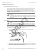
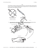
The TT210 power/accessory cable connects the TT210 system terminal to the trailer’s 7-way
electrical system. The cable also interconnects any optional accessories to the TT210
system terminal. The three optional accessories allow customers to optimize the system with
a cargo sensor, door sensor, and/or an auxiliary sensor.
The blue wire is crimped to a fuse holder that has a 3-amp, fast-acting ATM type automotive
fuse and connects to pin 7 of the 7-way. The white wire connects to pin 1 of the 7-way. The
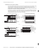
following illustration shows the various cable assemblies.
10AAA_12
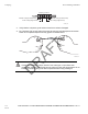
Dry Van Cable Assembly Wiring Diagram
BLU 16
WHT 16
BLU 20
WHT 20
BLU 20
WHT 20
BLK 20
BLK 20
GRN 20
YEL 20
BRN 20
RED 20
RED 20
BLK 20
GRA 20
ORN 20
P2
1
2
4
5
3
6
1
2
E
4
3
7
5
6
8
9
10
( EXT_PWR_IN)
(PWR_GND)
(REFFER_PWR_IN (NC ))
(SOLAR_PWR_IN (NC))
(CARGO_SENSOR_PWR)
(CARGO_SENSOR_TX)
(CARGO_SENSOR_RX)
(GND)
(AUX_SENSOR)
(DOOR_SENSOR)
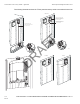
10AAA_14
P11P1
B8
A8
B1
A4
B4
B3
A3
A5
A6
A7
BLU 16
WHT 16
BLK 20
GRA 20
ORN 20
GRN 20
YEL 20
BRN 20
RED 20
1
2
3
7
5
6
8
4
9
10
(AUX_SENSOR)
(DOOR_SENSOR)
(EXT_PWR_IN)
(PWR_GND)
(SOLAR_PWR_IN )
(CARGO_SENSOR_TX)
(CARGO_SENSOR_RX)
(GND)
(CARGO_SENSOR_PWR)
(N/C)
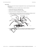
TT210 Retrofit Cable Assembly Wiring Diagram
(for use with existing TT200 installations)
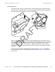
BLU 16
WHT 16
ORN 20
GRA 20
BLU 20
WHT 20
BLK 20
GRN 20
YEL 20
BRN 20
RED 20
P2
EI
1
2
4
3
7
5
6
8
9
10
(PWR_GND)
(REFFER_PWR_IN)
(SOLAR_PWR_IN )
(CARGO_SENSOR_TX)
(CARGO_SENSOR_RX)
(GND)
(AUX_SENSOR)
(DOOR_SENSOR)
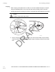
Reefer Cable Assembly Wiring Diagram
( EXT_PWR_IN)
(CARGO_SENSOR_PWR)
BLK 20
BLK 20
3
4
2
1
5
6
3X (16)
10AAA_13
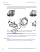
10AAA_15
BLU 20
WHT 20
BLK 20
GRN 20
YEL 20
BRN 20
RED 20
GRA 20
ORN 20
( EXT_PWR_IN)
(PWR_GND)
(REFFER_PWR_IN (NC
))
(SOLAR_PWR_IN (NC))
(CARGO_SENSOR_PWR
)
(CARGO_SENSOR_TX)
(CARGO_SENSOR_RX)
(GND)
(AUX_SENSOR)
(DOOR_SENSOR)
1
2
4
3
7
5
6
8
9
10
1
2
4
5
3
6
P1
P2
Cargo Only Cable Assembly Wiring Diagram