
User's Manual

QDBS–Broadband Hardware
- 26 -
QUALCOMM Confidential and Proprietary
MAY CONTAIN U.S. EXPORT CONTROLLED INFORMATION
80-D9001-1 Rev. A
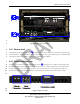
1
2
3
4
5
6
7
8
9
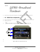
4.2.1. Radio Node (RN)
The RN provides radio resources and maintains radio links with the Access Terminal (AT). The RN
implements the Physical and Media Access Control (MAC) layers of the EV-DO protocol stack.
The RN is analogous to the BTS in the QDBS-Cellular.
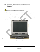
4.2.2. Power Distribution Unit (PDU)
The PDU is a power controller that provides AC power, EMI/RFI filtering, and spike/surge
protection to the components in the transit case. While the PDU has a master power switch and
eight momentary touch-switches that control the eight individual AC line receptacles, these switches
should not be turned on or off manually, as they are controlled by the OA&M computer.
CAUTION: Turning off the components manually using the PDU’s individual
(numbered) switches, may cause irreparable damage to the components.
10
11
12
4.2.3. Radio Frequency Front End (RFFE)
WARNING: Do not begin radiating an RF signal unless the appropriately loaded
antennas are connected to the RF terminals (TxRx0 and Rx1 of the RAN Connector
Interface Panel). Exposure to high levels of RF energy could result, causing bodily
injury.
13
14
15
16
17
18
19
20
21
22
23
24
25
26
27
28
29
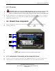
The RFFE is a single sector, 20 W power amplifier that boosts the signal from the RN sector to the
Tx/Rx0 and Rx1 antennas, resulting in greater coverage area. When the RN is used with the RFFE,
the radio is referred to as macro-cell. Each RN can support up to three sectors (each sector requiring
its own RFFE). The basic QDBS–Broadband, however, includes only one RFFE and can therefore
accommodate only one macro-sector. Additional RFFEs may be added to the QDBS–Broadband
(up to three per RN) to increase the number of macro-sectors.
The RFFE contains an internal Ethernet controller with Digital and Analog signals. The OAM
laptop controls the RFFE output power level, calibration, output protection and status monitoring
via the Ethernet controller. The RN RF output is connected to the RFFE input through Sub-
Miniature version A (SMA) connectors on the back of the RFFE and on the front the RN. The
RFFE output is connected to the Tx/Rx0 and Rx1 antennas using two N-type connectors (one for
transmitting and one for receiving) on the Radio Case CIP.
The front of the RFFE is shown in Figure 5. The rear of the RFFE is denoted with in Figure 7.