
User's Manual


Setting Up the QDBS–Broadband
- 38 -
QUALCOMM Confidential and Proprietary
MAY CONTAIN U.S. EXPORT CONTROLLED INFORMATION
80-D9001-1 Rev. A
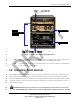
1
2
3
4
5
6
7
8
9
Frequency Electromagnetic Fields, 3 kHz to 300 GHz”" are being meet, when
measured in accordance with the ANSI/IEEE C95.3-1992 “Recommended Practice
for the Measurement of Potentially Hazardous Electromagnetic Fields - RF and
Microwave” procedure. Exposure to excessive levels of RF radiation may cause
serious bodily harm.
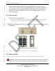
5.3.1. Pico-cell mode
To connect a pico-cell antenna:
1.
Connect the 30 dB RF loads to the ports labeled TxRx 0 (transmit port) and Rx 1
(Receive Diversity) of the Radio Case CIP, (see Figure 15 for more details).
NOTE: This 30 dB load is required to attenuate the transmit signal coming out of the
20 W RFFE.
10
11
12
13
14
15
16
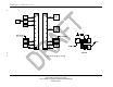
Figure 15: RF attenuators for pico-cell operation
2.
Connect a wire whip antenna to each of the 30 dB RF loads.
5.3.2. Macro-cell mode
See [10] for additional information on cellular antenna selection and installation guidelines.
WARNING: Follow all manufactures procedures and precautions when mounting the
antennas on a mast, tower, or vehicle to ensure they are securely mounted. Failure to
17
18