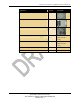
Unpacking and Inspecting QDBS–Broadband Hardware Equipment Quantity Description Ethernet Cable (Radio-Network) 1 Attenuators 2 Whip Antennas 2 OA&M computer (with Power Adapter) 1 Optional for use with QDBS-Cellular overlay. Ethernet cables for the OA&M computer 2 Optional for use with QDBS-Cellular overlay. Software Disks (CD-ROM and DVD) Documentation - 23 QUALCOMM Confidential and Proprietary MAY CONTAIN U.S. EXPORT CONTROLLED INFORMATION 80-D9001-1 Rev.
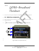
Section 4 QDBS–Broadband Hardware 1 This section provides specific descriptions of the QDBS–Broadband hardware components. 2 4.1. Radio Case components 3 4 Figure 5 identifies the major components of the Radio Case. Each component is described in the following subsections. 5 Note: Some Radio components are mounted in the rear of the transit case. 6 7 Figure 5: Radio Case components (front view) - 24 QUALCOMM Confidential and Proprietary MAY CONTAIN U.S.
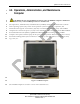
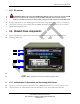
QDBS–Broadband Hardware 1 2 3 4 5 6 7 8 9 10 11 12 4.2. Operations, Administration, and Maintenance Computer CAUTION: Do not install additional software onto the OA&M computer. Additional software may cause OA&M operations to malfunction. The Operations, Administration, and Maintenance (OA&M) computer is installed with a CentOS Linux operating system (OS), and is used to perform system configuration, operation, and maintenance through the user interface (UI) and/or command line interface (CLI).
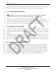
QDBS–Broadband Hardware 1 4.2.1. Radio Node (RN) 2 3 4 The RN provides radio resources and maintains radio links with the Access Terminal (AT). The RN implements the Physical and Media Access Control (MAC) layers of the EV-DO protocol stack. The RN is analogous to the BTS in the QDBS-Cellular. 5 4.2.2. Power Distribution Unit (PDU) 6 7 8 9 The PDU is a power controller that provides AC power, EMI/RFI filtering, and spike/surge protection to the components in the transit case.
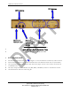
QDBS–Broadband Hardware 1 2 Figure 7: Radio Case (rear panel view) 3 4.2.4. Connector Interface Panel 4 5 The Connector Interface Panel (CIP) is a cable pass-through panel designed to make connecting and disconnecting the various serial and Ethernet connections in the transit cases easier. The CIP is located in the rear of the transit case and is denoted with in Figure 7, while CIP detail is shown in Figure 8. 6 7 - 27 QUALCOMM Confidential and Proprietary MAY CONTAIN U.S.
QDBS–Broadband Hardware 1 Figure 8: Detail of the Radio Case CIP 2 3 4.2.5. Ethernet switch 4 5 6 7 The Ethernet switch denoted with in Figure 7 is used for Ethernet connectivity and Local Area Network Internet Protocol (LAN IP) communications. The Ethernet switch has 16 10/100 Mb/s auto-speed Ethernet ports and built-in link and activity lights. Access to the switch is from the rear of the Radio Case.
QDBS–Broadband Hardware 1 2 3 4 4.2.6. RF antennas WARNING: When operating the QDBS–Broadband in pico-cell mode, install a 30 dB attenuator between the transmit port of the RAN CIP and the transmit antenna. Failure to install the attenuator may result in dangerous RF exposure and bodily harm. 5 6 7 For pico-cell operation, two small magnetic-mounted wire-whip RF antennas (one for transmitting and one for receiving), are provided with the QDBS–Broadband.
QDBS–Broadband Hardware 1 2 implements policies that determine which resources and services a valid user may access, and the accounting function keeps track of time and data resources used for billing and analysis. 3 4.3.2. Power Distribution Unit (PDU) 4 5 CAUTION: Turning off the components manually, using the PDU’s individual (numbered) switches may cause irreparable damage to the components.
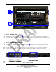
QDBS–Broadband Hardware 1 Figure 10: RNC case (rear view) 2 3 4.3.5. Ethernet switch 4 5 6 The Ethernet switch denoted with in Figure 10 is used for Ethernet connectivity and LAN IP communications. The Ethernet has sixteen 10/100 Mbps auto-speed Ethernet ports and built-in link and activity lights. The switch is accessed from the rear of the RAN. 7 4.3.6.
QDBS–Broadband Hardware 1 4.3.7. Serial console 2 3 A serial console panel denoted with components of the Network Case. 4 4.3.8. 120V Convenience outlets 5 6 7 The 120 VAC outlets denoted with in Figure 10 provide power for additional equipment needed during the operation of the system. Typically, these outlets support a phone charger or a laptop power adapter. These outlets are not intended to supply power to any high wattage device.
QDBS Release 3.0 Hardware Overview CASE 1 (RAN) ETHERNET SWITCH W21 DIVERSITY ANTENNA W22 DIAGNOSTIC I/O PANEL J1 ETH 1 iBSC GPS ANT COM 1 USB W48 W5 W47 LIGHTENING ARRESTOR W1 W49 W2 PWR GPS ANT 1PPS OUT RS232 W44 W3 GPS TOD 1PPS IN1 MAIN ETH iPA3 S3 Tx/Rx 0 S3 Rx 1 iBTS iPA2 S2 Tx/Rx 0 W57 GND S2 Rx 1 19.
QDBS Release 3.0 Hardware Overview 1 2 3 Figure 13: AC power wiring – 34 – QUALCOMM Confidential and Proprietary MAY CONTAIN U.S. EXPORT CONTROLLED INFORMATION 80-D9001-1 Rev.
Section 5 1 Setting Up the QDBS–Broadband 5.1. Site preparation 2 3 4 5 6 WARNING: Grounding the QDBS–Broadband to an appropriate ground is required to prevent injury or death in the event of a lightning strike. Depending on your deployment scenario, you can ground each QDBS–Broadband case grounding lug to facility ground by using grounding rods and cables, or ground to a vehicle-frame. Grounding equipment is not included with the QDBS–Broadband.
Setting Up the QDBS–Broadband 1 5.2.1. Setup sequence 2 3 See Figure 14 and Error! Reference source not found. for help on identifying the locations of items called out in the setup sequence. 4 To set up the QDBS–Broadband transit cases: 5 1. Press the red pressure relief valve on each case to relieve any pressure differences. 6 7 2. Remove the covers from the ends of the transit cases by unscrewing the captive threaded thumbscrews. 8 3.
Setting Up the QDBS–Broadband 1 Figure 14: Connections on the QDBS–Broadband 2 3 4 10. If the QDBS–Broadband is to be connected to a data network, connect the external network’s Ethernet cable to the PDSN port on the Radio Case CIP. 5 6 11. Connect both the Radio Case and Network Case AC power cables to a minimum of a 15A, 120V AC power supply. 7 5.3.
Setting Up the QDBS–Broadband 1 2 3 4 5 6 7 Frequency Electromagnetic Fields, 3 kHz to 300 GHz”" are being meet, when measured in accordance with the ANSI/IEEE C95.3-1992 “Recommended Practice for the Measurement of Potentially Hazardous Electromagnetic Fields - RF and Microwave” procedure. Exposure to excessive levels of RF radiation may cause serious bodily harm. 5.3.1. Pico-cell mode To connect a pico-cell antenna: 8 9 1.
Setting Up the QDBS–Broadband 1 2 do so may result in the antenna detaching from the mounting surface and seriously injuring personnel. 3 To connect a macro-cell antenna: 4 5 6 7 1. Connect the two macro-cell antennas (Transmit and Receive) to the desired mounting structure. NOTE: The two antennas should be at least five (5) feet apart for receive signal diversity. 8 9 2. Connect one end of the ½ inch diameter RF coax cable to bottom of the Transmit antenna. 10 3.
Section 6 Setting Up QDBS– Broadband Remote Radio Case(s) 1 2 3 The basic QDBS–Broadband system has a single Radio Case. This single Radio Case is capable of providing broadband coverage over a large geographic area. If more coverage is required, additional Radios may be connected to the QDBS–Broadband. 4 5 6 7 8 9 The initial Radio Case provided as a part of the basic QDBS–Broadband is referred to as a “local” Radio, since this Radio is physically in the same location as the Network Case.
Setting Up QDBS–Broadband Remote Radio Case(s) 1 6.1. Remote Radio Case connectivity 2 3 4 5 The remote RN is connected to the QDBS–Broadband using IP. A connection must be established between the Ethernet switch of the remote Radio Case and the Ethernet switch of the Network Case. This connection must be of adequate bandwidth to support the signaling and traffic requirements between the remote Radio and the components of the Network Case. 42 QUALCOMM Confidential and Proprietary MAY CONTAIN U.S.
Section 7 Setting Up the QDBS–Broadband & QDBS–Cellular in Overlay 1 7.1. Hardware setup 2 3 4 5 The QDBS–Broadband can be configured with a QDBS–Cellular to provide overlay coverage of Cellular 1x-RTT and Broadband EV-DO Rev. A coverage. The setup consists of two Radio Cases, QDBS-Cellular and QDBS-Broadband. The two QDBS systems are interconnected to provide overlay coverage. 6 7.2. Overlay system setup 7 1. Set up the QDBS–Cellular as described in the QDBS-Cellular Hardware Setup Guide.