
User's Guide
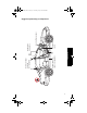
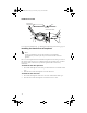
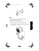
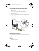
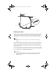


Table Of Contents
- Introduction
- Operation
- Installation
- Index

21
Installation
Whether the vehicle ignition has an ACC position or not, connect:
❑ Black lead ground (GND) to a clean unpainted metallic part of the
vehicle.
❑ Green lead (STEREO MUTE) to the audio system, if applicable.
❑ Red lead to the positive terminal of the vehicle battery.
❑ If the vehicle ignition has an ACC position, connect the yellow lead
to the Power Sense ACC position.
❑ If the vehicle ignition does not have an ACC position, connect the
yellow lead to the ON position of the ignition (Power Sense).
2. Connect the microphone and speaker to the GEM.
3. Connect the ODU cables to the outdoor unit and to the cradle.
4. Connect the cellular antenna (not included).
5. Connect the cradle cable to the GEM.
6. Connect the data cable (not included) to the GEM.
7. Connect the optional privacy handset or privacy headset to the GEM.
8. Connect the car interface cable to the GEM.
Caution
Exceeding the following input voltage and current values causes
the power fuse to open, and it will have to be replaced.
■ Maximum input voltage is 16.0 volts.
■ Maximum input current is 4000 mA.
Notes on cable routing
■ If possible, use existing slots and channels in the vehicle for connection.
■ Route the cables so that they will not tangle or interfere with the
movement of seats, pedals, and emergency brakes.
■ Avoid routing cables under floor mats in foot traffic areas so they will
not catch on your feet.
■ Route the cables so that they will not cause electrical interference.
■ Be sure to cut the car interface cable to the necessary length, and then
install the fuse holders where they are easily accessible. See
Connection diagram, page 20.
■ Be sure that the connector between GCK-10 and GCK-11 is inside the
vehicle. See figure below.
80-98438_book.book Page 21 Thursday, July 8, 1999 4:08 PM