
User's Manual
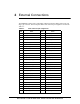
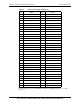
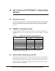
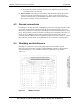
Table Of Contents

80-JA863-1 Rev. A 18 QUALCOMM Confidential and Proprietary
MAY CONTAIN U.S. AND INTERNATIONAL EXPORT CONTROLLED INFORMATION
FENWAY-2 Global User Guide for UMTS/GSM RF Integration
NOTE These FENWAY-2 shields must not be removed.
The host device is a hostile environment for RF transceivers, making the shields
absolutely necessary. Potential interference sources include the following:
Noise or ripple on the DC power supply voltage input lines, including transients due to
switching-mode power supplies or host operating mode changes.
High-speed digital logic transitions – The fast rising and falling edges include high
frequency harmonics that can fall into the FENWAY-2 Rx and/or Tx passbands. Host
circuits most likely to cause problems are the microprocessor, memory, and its
displays and display drivers.
Clocks – Also due to their high-speed transitions.
Other wireless devices, if not integrated onto the FENWAY-2 module, whether
integrated into the host device or external, such as WLAN (802.11) and Bluetooth®
devices. Transmit channels and their associated wideband noise can jam the
FENWAY-2 receivers, and even their LO frequencies, digital logic, or clock signals
can be disruptive.
Careful design is required to minimize the interference. FENWAY-2 performance
parameters, such as receiver sensitivity and transmitter spurious signals, should be
evaluated to confirm adequate grounding and shielding, location of the FENWAY-2
antennas, and perhaps even placement and routing of host device functions. This
evaluation should be performed for all FENWAY-2 operating bands.
4.5 Antenna considerations
As mentioned in Section 4.4, the location of the antenna elements is critical to FENWAY-2
RF performance. Routing the connecting coaxial cables could also impact FENWAY-2
performance; they should be routed away from corruptive noise sources (like the
switching-mode power supplies, LCD assemblies, microprocessor, memory, etc.).