
User's Manual
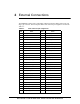
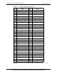
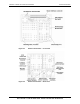
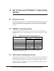
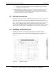
Table Of Contents

80-JA863-1 Rev. A 17 QUALCOMM Confidential and Proprietary
MAY CONTAIN U.S. AND INTERNATIONAL EXPORT CONTROLLED INFORMATION
FENWAY-2 Global User Guide for UMTS/GSM RF Integration
If Rx diversity and GPS position location are not supported, leave the unused
secondary antenna unconnected.
RF Feed points. The primary and secondary, GPS, Bluetooth and WLAN antenna
feed point locations are identified in Figure 2-1. These can be used to integrate
antenna elements directly to the FENWAY-2 module without coaxial cables which
may result in a smaller overall system solution.
4.3 Ground connections
Grounding is extremely important to FENWAY-2 performance. The main system ground
connections are mechanical, implemented by the ground clips identified in Figure 2-1.
Use these ground clips to ensure proper grounding. If system level design does not allow
use of these grounds, extensive performance testing must be completed to show they are
not necessary. In addition to these primary ground connections, the card’s 120-pin
connector provides additional electrical ground connections as listed in Table 2-1, and the
RF connectors provide the RF return paths that are also connected to system ground.
4.4 Shielding and interference
Shielding is an extension of the system ground and must be installed to prevent
interference between the host computer and the FENWAY-2 platform. The platform is
fully shielded (Figure 4-1) in accordance with FCC regulations (see [1] listed in
Table 1-2).
Figure 4-1 FENWAY-2 shields