
User's Manual
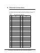
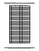
Table Of Contents

80-JA863-1 Rev. A 18 QUALCOMM Confidential and Proprietary
MAY CONTAIN U.S. AND INTERNATIONAL EXPORT CONTROLLED INFORMATION
FENWAY Global User Guide for UMTS/GSM RF Integration
The host device is a hostile environment for RF transceivers, making the shields
absolutely necessary. Potential interference sources include the following:
Noise or ripple on the DC power supply voltage input lines, including transients due to
switching-mode power supplies or host operating mode changes.
High-speed digital logic transitions – The fast rising and falling edges include high
frequency harmonics that can fall into the FENWAY Rx and/or Tx passbands. Host
circuits most likely to cause problems are the microprocessor, memory, and its
displays and display drivers.
Clocks – Also due to their high-speed transitions.
Other wireless devices, if not integrated onto the FENWAY module, whether
integrated into the host device or external, such as WLAN (802.11) and Bluetooth®
devices. Transmit channels and their associated wideband noise can jam the FENWAY
receivers, and even their LO frequencies, digital logic, or clock signals can be
disruptive.
Careful design is required to minimize the interference. FENWAY performance
parameters, such as receiver sensitivity and transmitter spurious signals, should be
evaluated to confirm adequate grounding and shielding, location of the FENWAY
antennas, and perhaps even placement and routing of host device functions. This
evaluation should be performed for all FENWAY operating bands.
4.5 Antenna considerations
As mentioned in Section 4.4, the location of the antenna elements is critical to FENWAY
RF performance. Routing the connecting coaxial cables could also impact FENWAY
performance; they should be routed away from corruptive noise sources (like the
switching-mode power supplies, LCD assemblies, microprocessor, memory, etc.).