
User's Guide

D
O
N
O
T
C
O
P
Y
Preliminary
Page 8 • AP User’s Guide Atheros Confidential and Proprietary
October 2001 Subject to change without notice.
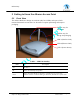
2.3 AP Network Attachment and Configuration
AP Network Configuration and Network Boot
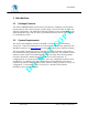
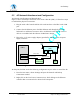
Figure 1 shows an example connection of the AP to a Host PC (HPC). Follow these steps
to establish the physical connections:
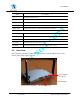
1. Plug the serial cable from the AP RS-232 serial interface to the HPC serial COM
port.
2. Connect the AP Ethernet port to the HPC Ethernet card through the Ethernet
hub/switch or an Ethernet crossover cable. An Ethernet switch/hub or crossover
cable is not included with the Atheros AP Reference Design.
3. Plug in the 3.3 V power supply adapter (provided by Atheros) to the AP power
supply connector.
Figure 1 – Connection Between AP and Host PC
At this point, the HPC needs the following configuration steps in order to control the AP:
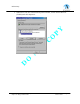
1. From the Start menu, choose Settings and open the Network and Dial-up
Connections window.
2. Right-click on the Local Area Connection icon, which belongs to the Ethernet
controller that is connected to the AP and select Properties.
Host PC
(HPC)
Ethernet Port
Serial Cable
Etherne
t Cable
Atheros Access Point
(AP)
Ethernet
Hub/Switch
COM Port
COM
Port
Ethernet
Port
Power
Power
Supply
Ethernet Cable