
User Manual Part 7
User Guide to Q4000/QPRO
Document Number 1135-4713 Rev G
THIS DOCUMENT CONTAINS CONFIDENTIAL AND PROPRIETARY INFORMATION OF QUAKE GLOBAL CORPORATION. IT MAY BE USED BY
RECIPIENT ONLY FOR THE PURPOSE FOR WHICH IT WAS TRANSMITTED AND WILL BE RETURNED UPON REQUEST OR WHEN NO LONGER NEEDED
BY RECIPIENT. DISCLOSURE TO UNAUTHORIZED THIRD PARTIES OR DUPLICATION WITHOUT THE EXPRESS WRITTEN PERMISSION OF QUAKE
GLOBAL IS PROHIBITED.
Page 132
CONFIDENTIAL
Information classified Confidential
-
Do not copy (See last page for obligations)
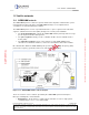
The term “desirable Gateway” refers to the Desired Gateways List that is maintained in
the modem’s Non-Volatile Memory (NVM). If no list has been entered into the modem,
all Gateways are considered desirable. If a Desired Gateways List has been entered,
however, communications are only allowed (or not allowed, depending on how the list is
configured) with those gateways specified in the list.
The maximum mobile originated message size through the Iridium network is 340 bytes.
The maximum mobile terminated message size is 270 bytes.
For roaming applications that demand the absolute minimum message latency, it is suggested to
send two messages: one as a Globalgram, and the other as a message or report. This ensures
that both of these delivery avenues are utilized, but may result in higher airtime costs.
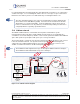
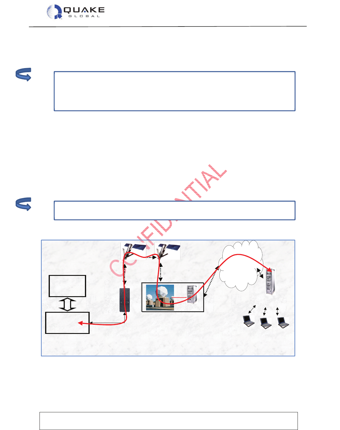
13.2 Iridium network
The Iridium Satellite Network is a world-wide, two-way data communication system.
Communications between modems and the Iridium ground network are accomplished via a
constellation of low-earth orbit (LEO) satellites. There are 66 operational satellites with additional
spares that operate in 6 polar planes with pole to pole coverage at all times.
The ground network is comprised of the System Control Segment and gateways used to connect
to the terrestrial data networks. The System Control Segment is the central management
component for the Iridium Satellite Network. It provides support and control services for the
satellite constellation and delivers satellite tracking data to the gateways.
Figure 13-2: Iridium network diagram
Iridium Gateway
SBD Network
Equipment
Internet
Email
End User Applications
Value Added Reseller
Host System
RS232 Serial
Interface
Microprocessor
Based
System
Sensor or
other
inputs/outputs
Iridium L-Band
Transceiver
Mobile
Application
[MA]
1,2,3,7,9
2,7,8
3,6,8
4,55
Note:
Note: