
User Manual Part 1


User Guide to Q4000/QPRO
Document Number 1135-4713 Rev G
THIS DOCUMENT CONTAINS CONFIDENTIAL AND PROPRIETARY INFORMATION OF QUAKE GLOBAL CORPORATION. IT MAY BE USED BY
RECIPIENT ONLY FOR THE PURPOSE FOR WHICH IT WAS TRANSMITTED AND WILL BE RETURNED UPON REQUEST OR WHEN NO LONGER NEEDED
BY RECIPIENT. DISCLOSURE TO UNAUTHORIZED THIRD PARTIES OR DUPLICATION WITHOUT THE EXPRESS WRITTEN PERMISSION OF QUAKE
GLOBAL IS PROHIBITED.
Page 27
CONFIDENTIAL
Information classified Confidential
-
Do not copy (See last page for obligations)
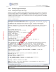
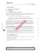
The figure below shows a typical Orbcomm satellite pass:
Figure 3-1: ORBCOMM satellite pass
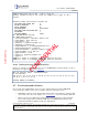
Note that in the figure below, the area of weakest radiation is directly above 90° using a whip
antenna. The area of strongest radiation is at 1/2Ȝ. The gain increases as the angle approaches
0. The size of the ground plane affects the look angle of the antenna pattern. Maximum gain is
at 10° - 30° above ground plane. Reducing the ground plane raises the look angle vertically;
increasing the ground plane lowers the look angle horizontally.
Figure 3-2: ORBCOMM areas of radiation
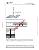
3.1.1.3 ORBCOMM ground plane
The most common means of producing a low angle of radiation from an antenna is to work the
radiator against a simulated ground called a Ground Plane. A ground plane may be made from a
large metal sheet or several wires or rods radiating from the base of the radiator.
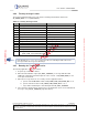
Table 3-1: Ground plane - simulated ground
Antenna Ground Plane
1/8 Whip 12” Diameter
12” x 12”
1/4 Whip 24” Diameter
24” x 24”
1/2 Wave Not required