
Data Sheet

QPRO Technical Data Sheet
Document 1137-0901, REV K 10
2.3 System Overview and Signal Descriptions
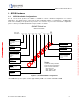
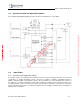
The following System Block Diagram describes the basic functional blocks of the QPRO:
Figure 2-2, QPRO System Block Diagram for Fully Loaded Configuration
2.4 Input Power
2.4.1 Internal Power Supply Description
The QPRO contains the required internal regulation and reverse bias/overvoltage protection to meet J1455
specifications for 12VDC and 24VDC systems. DC power of +6VDC to +32VDC is supplied through pin 1
(BATT+) and pin 2 (GND) of the multi-pin connector. The ground pins are connected directly to the chassis of
the QPRO. It is recommended that the power supply feeding the QPRO be protected with a fast-blow fuse
sized appropriately per the expected current draw. Current draw is dependent on the features and options
that are installed and operating. See Table 2-2, QPRO Power Consumption, Q4000 Power Consumption, for
typical power consumption.
Information classified Confidential
-
Do not copy (See last page for obligations)