R COLUMBIA BAY DIRECT VENT GAS APPLIANCE Tested and Listed by Owner’s Manual O-T L Portland Oregon USA US C OMNI-Test Laboratories, Inc. Installation and Operation Model: COLBAY-FS-B CAUTION DO NOT DISCARD THIS MANUAL • Important operating and • Read, understand and • Leave this manual with follow these instructions maintenance instructions party responsible for use for safe installation and included. and operation. operation.
and Welcome to the Quadra-Fire Family! Hearth & Home Technologies welcomes you to our tradition of excellence! In choosing a Quadra-Fire appliance, you have our assurance of commitment to quality, durability, and performance. meticulously fabricated and gold and nickel surfaces are hand-finished for lasting beauty and enjoyment. Our pledge to quality is completed as each model undergoes a quality control inspection.
- TABLE OF CONTENTS - A. B. C. D. E. F. G. H. Appliance Certifications ......................4 Glass Specifications ............................4 BTU Specifications ..............................4 High Altitude Installations ....................4 Non-Combustible Materials .................4 Combustible Materials ........................4 Electrical Codes ..................................4 Requirements for the Commonwealth of Massachusetts ......5 A. Design & Installation Considerations .................
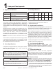
1 fications fication MODEL: Columbia Bay FS LABORATORY: OMNI Test Laboratories, Inc. 061-S-17b-5 TYPE: Direct Vent Gas Heater STANDARD: ANSI Z21.88a-2000ּCSA 2.33a-M00 ּUL307bּCAN/CBA 2.17-M91 Model The product is listed to ANSI standards for “Vented Gas Appliance Heaters” and applicable sections of “Gas Burning Heating Appliances for Manufactured Homes and Recreational Vehicles” and "Gas Fired Appliances for use at High Altitudes".
NOTE: The following requirements reference various Massachusetts and national codes not contained in this document.
2 A Quadra-Fire direct vent gas appliances are designed to operate with all combustion air siphoned from outside of the building and all exhaust gases expelled to the outside. No additional air source is required. CAUTION Check building codes prior to installation. • Installation MUST comply with local, regional, state and national codes and regulations. • Consult local building, fire officials or authorities having jurisdiction about restrictions, installation inspection, and permits.
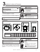
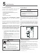
3 Appliance Location and Clearances NOTE: · Illustrations reflect typical installations and are FOR DESIGN PURPOSES ONLY. · Illustrations/diagrams are not drawn to scale. · Actual installation may vary due to individual design preference. Fire Risk Provide adequate clearance: • Around air openings • To combustibles • For service access Locate appliance away from traffic areas. When selecting a location for your appliance it is important to consider the required clearances to walls (see ). Fire Risk.
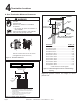
4 HORIZONTAL OVERHANG Fire Risk. Explosion Risk. Maintain vent clearance to combustibles as specified. • Do not pack air space with insulation or other materials. Failure to keep insulation or other materials away from vent pipe may cause fire. 2 FT. MIN. (See for specific clearances.) A B 6 in. (minimum) up to 20 in. 152 mm/508 mm 18 in. minimum 457 mm 20 in. and over 0 in.
(SeeNote Note2) 2) (S v v v v V = VENT TERMINAL A B D* X = AIR SUPPLY INLET = 12 inches ............. clearances above grade, veran(See Note 1) da, porch, deck or balcony = 12 inches ............ clearances to window or door that may be opened, or to permanently closed window. (Glass) = 18 inches ............. vertical clearance to unventilated soffit or to ventilated soffit located above the terminal *30 inches ............ for vinyl clad soffits and below electrical service F = 9 inches ...........
5 In order to comply with applicable codes and product warranties, use only following venting components: Hearth & Home Technologies (HHT) Security Chimney's Secure Vent Chimney System Selkirk Metalbestos AmeriVent Simpson Dura-Vent (SDV) ALL vent configuration specifications MUST be followed. • This product is tested and listed to these specifications. • Appliance performance will suffer if specifications are not followed.
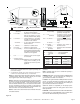
1. 2. 3. Measure the vertical distance from the center line of the flue pipe to the center of the 90° elbow. On the graph below, draw a horizontal line from that measurement on the vertical axis across until it intersects with the slanted line. From the point of this intersection, draw a vertical line to the bottom of the graph. The point at which this line meets the bottom line of the graph is the maximum length of the horizontal run.
HHW2 - Recommended for optimum performance. 90 DEGREE ELBOW PIPE LENGTH PIPE LENGTH WALL WALL THIMBLE THIMBLE COVER Fire Risk. Explosion Risk. Combustion Fume Risk. Use vent run supports per installation instructions. Connect vent sections per installation instructions. • Maintain all clearances to combustibles. • Do NOT allow vent to sag below connection point to appliance. Determine the desired location of the appliance.
WOOD SCREW CENTER OF HOLE CENTER LINE HOT WALL THIMBLE CENTER LINE PART HHW2 PART 841-0670 (Preferred) WALL THIMBLE NOTES: (1) The four wood screws provided should be replaced with appropriate fasteners for stucco, brick, concrete, or other types of sidings. NOTE: (1) Installation requires a minimum of 6 in. (152mm) horizontal run of vent with a 1/4 in. (6mm) rise run towards the termination. Each 1 ft. (305mm) of horizontal venting must include a 1/4 in. (6mm) rise.
VINYL SIDING APPLY SEALANT TO ALL FOUR SIDES SCREWS BOLT HORIZONTAL TOP TO VINYL STANDOFF Fire Risk. Explosion Risk. Maintain vent clearance to combustibles as specified. • Do not pack air space with insulation or other materials. Failure to keep insulation or other materials away from vent pipe may cause fire.
NOTE: VERTICAL TERMINATION CAP Maximum vertical rise allowable is 35 ft. (11m) ). NOTE: Maximum number of 45° elbows permitted for a vertical installation is eight, provided their installation does not decrease maximum allowable horizontal run (as specified by vent graph, on page 11). STORM COLLAR FLASHING FIRESTOP SUPPORT BOX 35 ft.
Set the gas appliance in its desired location. Drop a plumb bob down from the ceiling to the position of the appliance flue exit, and mark the location where the vent will penetrate the ceiling. Drill a small hole at this point. Next, drop a plumb bob from the roof to the hole previously drilled in the ceiling, and mark the spot where the vent will penetrate the roof. Determine if ceiling joists, roof rafters, or other framing will obstruct the venting system.
Continue to assemble pipe sections until the height of the vent (before adding the termination cap) meets the minimum code requirements as outlined in the current CAN/CGA-B149 Installation Codes (in Canada), the National Fuel Gas Code NFPA 54/ANSI Z223.1 (in USA), or local codes. Note that for steep roof pitches, the vent height must be increased. See Roof Pitch Table ( , on page 8).
Follow installation Steps 1 and 2 under vertical installation section, pages 15-16. Remove shingles or other roof covering as necessary to cut the rectangular hole for the support box. Cut the hole 1/8 in. (3mm) larger than the support box outline. Lower the support box through the hole in the roof until the bottom of the support box protrudes at least 2 in. (51mm) below the ceiling ( ). Align the support box both vertically and horizontally with a level.
TERMINATION CAP TOP ADAPTOR FLASHING EXISTING METAL CHIMNEY SYSTEM Pass the flex pipe down through the center of the chimney system, and center the top adapter on the top of the chimney pipe. Drill four 1/8 in. (3mm) diameter holes through the top adapter, and into the chimney top. Ensure that you are drilling into the metal on the chimney. Twist lock the high wind termination cap onto the top adapter . 4 in.
TERMINATION CAP TOP ADAPTOR MASONRY CHIMNEY RETRO CONNECTOR FLASHING FOUR MASONRY BOLTS RETRO CONNECTOR COVER 4 in. (102mm) FLEX LINER 90 DEGREE ELBOW Secure the flashing to the top of the masonry chimney using a bead of non-hardening sealant-adhesive. If the flashing is larger than the top of the chimney, cut and fold flashing as needed to fit chimney . DIRECT VENT PIPE CUT AND BEND FLASHING AS NEEDED TO FIT CHIMNEY CAUTION Ensure that existing chimney is functionally sound and clean.
Fire Risk. Explosion Risk. • Do not let the flex liner sag below the level at which it will connect to the appliance or connector. This could allow hot gas to become trapped and potentially become a fire hazard. The flex liner path should always be sloped up toward the termination cap. If additional lengths of flex liner are needed to span the chimney height, use a flex coupler to connect the pieces of flex liner together. Connect the flex to the coupler by using four sheet metal screws for each side ( ).
6 Before making gas connections ensure that the appliance being installed is compatible with the available gas type. Any natural or propane gas conversions necessary to meet the appliance and locality needs must be made by a qualified technician using Hearth & Home Technologies specified and approved parts. Lift the burner from the left side and slide left until free from the orifice receiver. Remove from the firebox and handle with care.
E Fire Risk. Explosion Risk. Disconnect any electrical cords and turn off gas supply to unit before proceeding if converting fuel on an appliance already fully installed. Remove upper and lower back shield. Loosen the set collars on the extension rods with the 3/32 in. Allen wrench. Remove the rods and adapter cap. D F Ensure that the rubber gasket is properly positioned and install the new HI/LO pressure regulator assembly to the valve using the new screws supplied with the kit.
Proper input pressures required for optimum appliance performance, gas line sizing requirements need to be followed from NFPA54. Fire Risk. Explosion Hazard. High pressure will damage valve. • Disconnect gas supply piping BEFORE pressure testing gas line at test pressures above 1/2 psig. • Close the manual shutoff valve BEFORE pressure testing gas line at test pressures equal to or less than 1/2 psig. Verify inlet pressures. • High pressure may cause overfire condition. • Low pressure may cause explosion.
Fire or Explosion Hazard • Gas build-up during line purge may ignite. • Purge should be performed by qualified technician. • Ensure adequate ventilation. • Ensure there are no ignition sources such as sparks or open flame. A small amount of air will be in the gas supply lines. When first lighting appliance it will take a short time for air to purge from lines. When purging is complete the appliance will light and operate normally.
7 See B5 below for recommended maximum lead length (two wire) when using wall thermostat/switch. NOTE: This appliance must be electrically wired and grounded in accordance with local codes or, in the absence of local codes, with National Electric Code ANSI/NFPA 70-latest edition or the 8. Ensure the thermostat is mounted level for accurate readings. 9. The thermostat should be mounted on an inside wall and not in direct line with the appliance convection air. 10.
THERMOPILE GAS PILOT IGNITOR THERMOCOUPLE IGNITOR Red 28 in. (711MM) ON/OFF SWITCH Red 28 in. (711MM) CAUTION VALVE CAUTION Label all wires prior to disconnection when servicing controls. Wiring errors can cause improper and dangerous operation. Verify proper operation after servicing. Shock hazard. • Replace damaged wire with type 105O C rated wire. • Wire must have high temperature insulation. Quadra-Fire • COLBAY-FS-B • 250-5195 Rev.
8 Appliance Setup Remove shipping materials from inside or underneath the firebox. Install approved accessories per instructions included with accessories. Refer to Section 12 for appropriate accessories. Shock or fire risk. Use ONLY optional accessories approved for this appliance. • Using non-listed accessories voids warranty. • Using non-listed accessories may result in a safety hazard. • Only Hearth & Home Technologies approved accessories may be used safely.
While still breakable, the logs do not become fragile until after the appliance is burned and they have cured. After curing, any handling must be done with care as breakage can easily occur. Holding both sides of the metal refractory brick piece, pull slightly together and rotate out of the firebox. 1 4 2 3 Install rear panel, gently wedging it between support shelf and baffle base. Install the brick brackets that are enclosed with the brick set.
that gas can contact them on all sides. Avoid stacking the embers on top of each other. NOTE: Do not block gas ports. Remove the grille: Slide the grille out of the slots in the existing door. Place right and left front logs on burner in the grooves provided on the burner surface. Remove the existing door from the appliance. Remove the crown from the existing door by removing four screws on the back side of the door assembly. Pull crown off door face. Install replacement door with glass onto appliance.
Turn off power supply. INCLUDED IN KIT: Blower; 2 female spade wire connectors. Remove blower housing from appliance, if necessary. TOOLS REQUIRED: Phillips head screwdriver. Disassemble housing if needed, retaining all fasteners, and remove the blower. Reassemble blower in housing using fasteners previously removed. Reinstall blower housing to appliance. Turn power supply back on.
Refer to the vent graph on page 11. If your installation falls within the range of the gray shaded area of graph, it may be necessary to make an adjustment to the vertical damper to improve the flame appearance in your appliance. OPEN CLOSE The shutter is located on the underside of the appliance, on the right side. To adjust the shutter, loosen the wingnut.. Retighten the wingnut after adjustment. The vertical damper adjustment is located on the right side of the unit behind the side curtain.
9 Read this entire manual prior to using the appliance. Failure to follow the instructions may result in property damage, bodily injury, or even death. Remove all shipping materials from inside and/or underneath the firebox. Improper installation, adjustment, alteration, service or maintenance can cause injury or property damage. Refer to the owner’s information manual provided with this appliance. For assistance or additional information consult a qualified installer, service agency or the gas supplier.
FOR YOUR SAFETY READ BEFORE LIGHTING WARNING: If you do not follow these instructions exactly, a fire or explosion may result causing property damage, personal injury or loss of life A. This appliance has a pilot that must be lit manually. When lighting the pilot, follow these instructions exactly. B. BEFORE LIGHTING, smell around the appliance area for gas. Be sure to smell next to the floor because some gas is heavier than air and will settle on the floor.
CAUTION When you light your appliance, you may notice that it produces heat which does have an associated odor or smell. If you feel this odor is excessive it may require the initial three to four hour continuous burn on high followed by a second burn up to 12 hours to fully drive off any odor from paint and lubricants used in the manufacturing process. Condensation on the glass is normal. NOTE: The appliance should be run three to four hours on the initial start-up. Turn it off and let it cool completely.
10 With proper installation, operation, and maintenance your gas appliance will provide years of trouble-free service. If you do experience a problem, this troubleshooting guide will assist a qualified service person in the diagnosis of a problem and the corrective action to be taken. This troubleshooting guide can only be used by a qualified service technician. 1. After repeated triggering of the piezo button, the spark ignitor will not light the pilot. 2.
3. (Continued) c. Defective valve. Turn the valve knob to the ON position. Place the ON/OFF switch in the ON position. Check the millivolt meter at the thermopile terminals. The millivolt meter should read greater than 125mV. If the reading is acceptable, and if the burner does not come on, replace the gas valve. d. Plugged burner orifice. Check the burner orifice for stoppage. Remove stoppage. e. Wall switch or wires are defective. Follow the corrective action in Symptom and Possible Cause 1.a.
11 Although the frequency of your appliance servicing and maintenance will depend on use and the type of installation, a qualified service technician should perform an appliance check-up at the beginning of each heating season. CAUTION Handle glass assembly with care. NOTE: Clean glass after initial 3-4 hours operation. fi Risk of injury or property damage. • Turn off gas. • Turn off electricity to appliance. • Ensure appliance is completely cooled. • Replace front and glass, if removed.
Doors 1. Inspect for scratches, dents or other damage and repair as necessary. 2. Verify no obstructions to air flow. 3. Verify maintenance of proper clearance to combustible household objects. Gasket Seal, Glass Assembly and Glass 1. Inspect gasket seal and its condition. 2. Inspect glass for scratches and nicks that can lead to breakage when exposed to heat. 3. Confirm there is no damage to glass or glass frame, Replace as necessary. 4.
Page 40 Quadra-Fire • COLBAY-FS-B • 250-5195 Rev.
12 Dimensions are actual appliance dimensions. Use for reference only. For clearances refer to Section 3. A C D B E F G H I K J A 22-1/2 572 G 11-1/4 286 B 28-1/2 724 H 7-3/4 197 C 16 406 I 5 127 D 18-3/4 476 J 17-7/16 443 E 28-1/2 724 K 16 406 F 22-1/2 572 Quadra-Fire • COLBAY-FS-B • 250-5195 Rev.
6-1/2 in. 165 mm 6-9/16 in. 167 mm 9-7/16 in. 240 mm 6-9/16 in. 167 mm 9-1/4 in. 235 mm 6 in. 152 mm 6-5/8 in. 168 mm 6-5/8 in. 168 mm 9-3/4 in. 248 mm SLP45 SLP90 6-5/8 in. 168 mm 7-1/4 in. 184 mm 5-1/4 in. 133 mm 6-5/8 in. 168 mm 6-5/8 in. 168 mm 6-5/8 in. 168 mm 6-9/16 in. 167 mm 13-1/4 in. 337 mm 7-1/4 in. 184 mm SLP6 SLP4 6-5/8 in. 168 mm 6-9/16 in. 167 mm SLP12A SLP6A 6-5/8 in. 168 mm 6-5/8 in. 168 mm 49-1/4 in. 1251 mm 37-1/4 in. 946 mm 6-5/8 in. 168 mm 25-1/4 in.
TERMINATION KITS COMPONENTS SLP-WT-BK Ceiling Support / Wall Thimble, Black SLP-TRAP2 SLP-CCS-BK Cathedral Ceiling Support, Black SLP-TVHW Vertical Termination Cap - High Wind SLP6-BK 6 inch Pipe Length, Black SLP-SK-BK SLP4-BK 9 inch Pipe Length, Black Horizontal Termination Kit (includes 904B, 930D, SLK-01TRD) SLP12-BK 12 inch Pipe Length, Black SLK-SNKD Snorkel Kit SLP34-BK 24 inch Pipe Length, Black SLP36-BK 36 inch Pipe Length, Black SLP48-BK 48 inch Pipe Length, Black LINK-STOV
Hearth & Home Technologies Inc. LIMITED LIFETIME WARRANTY Hearth & Home Technologies Inc., on behalf of its hearth brands (”HHT”), extends the following warranty for HHT gas, wood, pellet, coal and electric hearth appliances that are purchased from an HHT authorized dealer.
(continued) WARRANTY CONDITIONS: 7KLV ZDUUDQW\ RQO\ FRYHUV ++7 DSSOLDQFHV WKDW DUH SXUFKDVHG WKURXJK DQ ++7 DXWKRUL]HG GHDOHU RU GLVWULEXWRU $ OLVW RI ++7 DXWKRUL]HG GHDOHUV LV DYDLODEOH RQ WKH ++7 EUDQGHG ZHEVLWHV 7KLV ZDUUDQW\ LV RQO\ YDOLG ZKLOH WKH ++7 DSSOLDQFH UHPDLQV DW WKH VLWH RI RULJLQDO LQVWDOODWLRQ &RQWDFW \RXU LQVWDOOLQJ GHDOHU IRU ZDUUDQW\ VHUYLFH ,I WKH LQVWDOOLQJ GHDOHU LV XQDEOH WR SURYLGH QHFHVVDU\ SDUWV FRQWDFW WKH QHDUHVW ++7 DXWKRUL]HG GHDOHU RU VXSSOLHU $GGLWLRQDO
R CONTACT INFORMATION: fi fi CAUTION Do NOT discard this manual. • Important operating and maintenance instructions included. • Read, understand and follow these instructions for safe installation and operation. • Leave this manual with party responsible for use and operation.