
Owner`s manual


January 29, 2014 7034-276 29
MT. VERNON AE
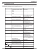
Figure 29.3
Depress Tab and
Snap Out Power
Supply
Remove
Left Side
Panel
Disconnect Wire Harness
from Bottom of Blower
Remove 2
Screws
Remo
ve
Righ
t Side
Panel
Figure 29.2
C. Convection Blower Replacement
1. Follow the proper shut down procedures as outlined on
page 21, Section 4.A.
2.
Removetheleftandrightsidepanelsbyremovingthe4
screws using a Phillips head screw driver. Figure 29.1.
3. Depressthetabontheleftsideandsnapoutthepower
supply. You do not need to disconnect any wires. Figure
29.1.
4.
Removethe2screwsatthebottomofthebackpanelso
therewillberoomtoremovetheblower.Figure 29.1
5.
Reachbehindtheblowerandreleasethelatchbypushing
thetopofthelatchtowardstheblower.Figure 29.2.
6. Rockthetopoftheblowerslightlyandliftup.Theblower
willpassaroundthecontrolboardandouttheleftsideof
the appliance.
7. Disconnect the wire harness from the bottom of the
blowerbydepressingthetabsonthesidesofthecon-
nector and then pulling to remove. Figure 29.1.
8. Re-connectwireharnesstothenewblower.
9. Installreplacementblowerbyplacingthebottomange
intotheopeningrstthenrotateblowerupintoposition.
10.
Whentheblowerisproperlypositionedthelatchwillengage
thenotchtoholdtheblowerinplace.Figure 29.3.
11.Re-securethebackpanel,snapthepowersupplyback
inandre-securethesidepanel(s).
E. Combustion (Exhaust) Blower Replace-
ment
1. Follow the proper shut down procedures as outlined on
page 21, Section 4.A.
2. Removetherightsidepanelbyremovingthe4screws
using a Phillips head screw driver. Figure 29.4.
3. It is not necessary or recommended to remove the hous-
ing to replace or service the combustion blower. You
only need to remove the motor and impeller.
4. Disconnectthe wire from the control board connection
points#1and#8.Depressthetabontheconnectorto
disconnectthewire(similartoatelephoneconnector).
See page 32 for the locations of #1 and #8.
5. Usingan11/32socketornutdriver,loosenthe(6)8x32
nuts securing the motor and impeller to the housing.
Rotatetheblowerandremovefromhousing.
6. Holdingthe black plastic body of the motor,rotate the
impeller counter-clockwise until blades line up with
opening in the housing and remove motor and impeller.
7. Ifthegasketbetweenhousingandmotorisdamagedit
willhavetobereplaced.Agasketisincludedwiththe
replacementblower.
8. Re-install in reverse order.
Notch
Latch
Latch Engaged
Figure 29.1
Loosen (6) Nuts
Remove
Side
Panel
Figure 29.4