QTech SMS Controller Quick Start Guide
QTech SMS Controller - Quick Start Guide – v1.4 – February 2014 2 Introduction The SMS Controller is a powerful cellular remote control unit. It uses text messages to provide multiple people with status conditions, alarms and control options. Setup and configuration of the SMS Controller is via “Workbench”, a user friendly PC application for Microsoft Windows 7/XP. Setup can be performed “offline” allowing you to pre-configure SMS Controllers. These configurations can then be saved for future use.
QTech SMS Controller - Quick Start Guide – v1.4 – February 2014 3 Aerial Connection Carefully connect the aerial. Do not operate the SMS Controller without an aerial connected. Refer to the aerial notes section on page 6 for alternatives. Power Supply Connection The SMS Controller is powered from an external 12-30 V DC supply. Connect the supply to the power connector, positive to the “+V” terminal, negative to “GND”. The third terminal on the right is not used.
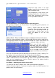
QTech SMS Controller - Quick Start Guide – v1.4 – February 2014 4 Follow the steps shown in the help bubbles to get the basic aspects of the SMS Controller set up. The configuration is really intuitive, user friendly and only takes a few moments. Click “Enter” to accept an entry or click in the help bubble to advance. System Information – This contains details about the system. The selections needed are the "Device Name", “County dialling prefix” (default is +64 for NZ) and “Service Provider”.
QTech SMS Controller - Quick Start Guide – v1.4 – February 2014 5 We recommend using a descriptive/the actual name e.g. “Site Security”, as this name will appear in all the text messages for this point. If you are controlling outputs, try to keep the name short, as you need to type the name in the text, e.g. “pump” would be a good suggestion as the control text would be “turn on pump”. The SMS Controller can automatically perform specified actions when something of interest happens.
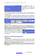
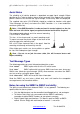
QTech SMS Controller - Quick Start Guide – v1.4 – February 2014 6 Digital Outputs The digital outputs are solid state devices designed to interface to a low power relays. When an output is on, it will be connected to the power supply negative, allowing current to flow into the output terminal to ground. + Supply When in the OFF state, they have a high impedance to ground and will float up to the power supply positive. The digital output LED will light up when the output is ON.
QTech SMS Controller - Quick Start Guide – v1.4 – February 2014 7 Aerial Notes The reliability of all cellular products is dependent on good signal strength. Before deciding on the Telco to choose, please check coverage. We suggest that a cellular phone is taken to site, to check the signal strength, ie how many “bars” are displayed.
QTech SMS Controller - Quick Start Guide – v1.4 – February 2014 8 Status LEDs PWR (Power) This LED is on when the device is powered on. OK Flashes to show the device is active and not locked up. ERR (Error) This LED flashes a number of times to indicate any errors.