Q80 – Telemetry Radio Owners Manual
Q80 Telemetry Radio Module Page 2 Manual Revision No. 1.04 Dated October 2012 Copyright 2000 to QTech Data Systems Christchurch, NEW ZEALAND Limited All rights reserved The circuit details and know how disclosed in this document are proprietary to QTech Data Systems Limited and shall remain the intellectual property of QTech Data Systems Limited.
Q80 Telemetry Radio Module Page 3 REVISION DETAILS 1.01 - April 2000 Original 1.02 - Nov 2001 Updated for Rev C Board 1.03 – Oct 2010 New logo, page layout and correction of aerial supply details 1.04 – Oct 2012 Updated address and inserted channel/DIP switch settings www.qtech.co.
Q80 Telemetry Radio Module Page 4 TABLE OF CONTENTS Revision Details..........................................................................3 Table of Contents .......................................................................4 Introduction ................................................................................5 The Product ................................................................................... 5 What’s in this Manual ...........................................................
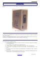
INTRODUCTION INTRODUCTION This revision 1.02 manual is for use with the Q80 – Telemetry Radio Module up to Rev B and Rev C printed circuit boards. Q80 – Telemetry Radio Module. The Product The Q80 – Telemetry Radio Module is a complete telemetry radio transceiver designed to complement the QTech range of RTU modules.
INTRODUCTION Throughout the manual NOTE’s and TIP’s (shown in green italic letters) are included to give related suggestions, explanations and additional information, etc. The Q80 – Telemetry Radio Module is referred to as the Q80 Module throughout this manual. QTech Data Systems Limited is referred to as QTech throughout this manual. Precautions The power should be removed from the module by removing the power connector before setting up and making any adjustments to the module.
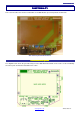
FUNCTIONALITY FUNCTIONALITY This section describes the functions and facilities of the Q80 Module up to Rev B printed circuit boards. Q80 Telemetry Radio Motherboard. Functional Descriptions The diagram below shows the generalised layout of the Q80 Motherboard and can be used to locate and identify the various parts and functions detailed in this section. www.qtech.co.
FUNCTIONALITY Q80 – Telemetry Radio Motherboard layout. Maxon Radio Module. The Maxon Radio module is a totally self contained state of the art fully synthesized radio transceiver. The picture to the right shows the Maxon radio module installed on the Q80 Motherboard. The key features of the Maxon Radio module include: Fully synthesised 16 channel receiver and transmitter. Each of the 16 channels can be programmed for: • • • 12.5 kHz or 25 kHz channel spacing. Simplex or repeater operation. 0.
FUNCTIONALITY Note The Technical Notes section of this manual describes the radio interface in detail and allows interfacing of the Q80 Module to customer specific equipment. Front Panel Status LED’s There are three status LED’s on the front panel of the Q80 Module. These status LED’s display the following Q80 Module status: ON The power is ON. MU The radio receiver is busy, i.e. the receiver mute is open. KY The radio transmitter is keyed ON. www.qtech.co.
FUNCTIONALITY CONFIGURATION This section describes how to configure the Q80 Maxon Radio Motherboard. The power should be removed from the module by removing the power connector before setting up and making any adjustments to the module. The Q80 Maxon Radio Module incorporates static discharge sensitive devices. Normal Anti Static Discharge precautions should be employed when setting up and making any adjustments to the module.
FUNCTIONALITY The receive and transmit levels are preset prior to delivery and should not normally require adjustment when the Q80 Module is to be used with a QTech RTU module. For applications with customer supplied equipment refer to the Technical Notes for adjustment details. Note The 600 ohm modem line terminating resistor in the QTech RTU modules should be removed, i.e. not installed. www.qtech.co.
CONNECTIONS CONNECTIONS CONNECTIONS This section describes the function and connections to the various connectors on the Q80 Module. Power Supply The Q80 Module is designed to operate with a DC power supply voltage of nominally 12 volt. The Q80 Module draws approximately 80mA in Standby, 100mA on Receive and 1.2A on Transmit at 5 Watts output. The power connector is a 3 way connector located on the bottom panel of the Q80 Module and is labelled ‘PWR’.
CONNECTIONS CONNECTIONS Radio Aerial The Maxon Radio Rx/Tx RF connector is located on the front panel of the Q80 Module. This connector is a 50 ohm BNC connector. The Q80 Module is not supplied with an aerial. QTech supply a number of suitable aerials; please contact us for further details. Suitable aerials include whips, folded dipoles and yagis. The aerial used must present 50 ohms to the Q80 Module BNC RF connector at the operating frequency.
TECHNICAL NOTES TECHNICAL NOTES This section describes the technical aspects of Q80 Module power supply and modem interface. Power Supply The Q80 Module is designed to operate with a DC power supply voltage of nominally 12 volt. The Q80 Module draws approximately 80mA in Standby, 100mA on Receive and 1.2A on Transmit at 5 Watts output. The DC power supply to the Q80 Module must be adequately smoothed and be free from noise and voltage transients.
TECHNICAL NOTES The remote power ON/OFF control line turns the NMOS FET transistor Q1 on and off via transistor Q2. The power will be ON when 12 volts is applied to the remote power ON/OFF control line and OFF when the remote power ON/OFF control line is grounded. Jumper J1, when installed, disables the remote power ON/OFF control. The remote power ON/OFF control line should be connected to the ‘+’ terminal of the Q22 DATRAN eXcel Module power connector.
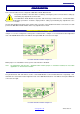
TECHNICAL NOTES Circuit details of Radio Interface. The opto isolators OPT1 and OPT2 provide isolation of the Maxon radio transmit key and busy lines between the Q80 module and associated equipment. Transmitter Transmitter Key The Maxon radio transmitter is keyed ON by pulling the TXKEY line to ground. The transmitter keyed KY LED3 will turn ON. The TXKEY line ON current is approximately 10mA.
TECHNICAL NOTES First set the transmit audio level. Feed a –3dBm 1800Hz audio signal into the audio terminals of the 6 way DIN Modem connector. Pin No1 and Pin No 2. Connect a deviation meter to the BNC RF connector terminated at 50 ohms. Key the transmitter on by pulling Pin No 4 of the 6 way DIN Modem connector to ground. Adjust VR2 for +/3kHz (+/- 1.8 kHz) transmitter deviation. Now set the receive audio level. Connect a dBV meter to the audio terminals of the 6 way DIN Modem connector.
TECHNICAL NOTES SPECIFICATIONS Power Supply DC 12 volts. Standby 80mA, Receive 100mA and Transmit 1.2A at 5 Watts output. Remote ON/OFF Module power can be remotely controlled by Q22 – DATRAN eXcel Module. Programmable The frequency synthesizer, channel spacing and power output are fully programmable. Frequencies VHF 148 – 174MHz UHF 400 – 440MHz (Proposed). UHF 450 – 480MHz UHF 480 – 520MHz (Proposed) Channel Spacing 12.5KHz or 25KHz. RF Output Programmable 0.5 to 5 watts in 8 steps per channel.
TECHNICAL NOTES WARRANTY & LIABILITY Subject to the under mentioned exemptions QTech Data Systems Limited undertakes to repair any manufacturing defects and replace or repair any faulty materials within (12) twelve months from the date of sale to the original purchaser. The exemptions referred to are: 1) Fair wear and tear 2 Faulty installation, misuse, neglect, accident and similar causes. 3) Equipment that does not bear the original Serial Number label or the label has been defaced or altered.
TECHNICAL NOTES OUT OF WARRANTY SERVICE Where the equipment is outside the (12) twelve month warranty period or is not otherwise covered by the warranty, then the service work will be carried out as detailed above with the exception that all labour, materials and freight will be charged at QTech’s rates applicable at the time of service. www.qtech.co.
QUICK FIND INDEX A adjustment audio level................................................ 10, 16 aerial connector................................................................ 13 audio level adjustment ..................................................... 10, 16 level receive ................................................................. 16 level transmit ................................................................ 16 C configuration.................................................................
USER NOTES USER’S NOTES __________________________________________________________________________________________ __________________________________________________________________________________________ __________________________________________________________________________________________ __________________________________________________________________________________________ __________________________________________________________________________________________ _______________________________
USER NOTES __________________________________________________________________________________________ __________________________________________________________________________________________ __________________________________________________________________________________________ __________________________________________________________________________________________ __________________________________________________________________________________________ ______________________________________________