
- QSC Professional Audio Amplifiers 2-Channel Low-impedance User Manual CX302, CX502, CX702, CX902, CX1102, CX254, CX404, CX204V, CX302V, CX602V, CX1202V


EN
9
Gain Controls
The Gain controls are recessed and can be adjusted with
a small screwdriver or flat tool. If desired, the Gain Con-
trol Security Cover can be installed to prevent changes
to the installer's settings.
Turn the gain controls clockwise to increase gain and
counter clockwise to decrease gain. The maximum volt-
age gain of the amplifier varies depending on the model
designation. Maximum voltage gain for each model is
shown on the front panel label in parentheses adjacent
the 0dB attenuation setting.
The Gain controls are marked in dB of attenuation. There
are 21 detents for repeatable adjustments. The upper 14
steps are about 1 dB each, and settings should normally
be made within this range. The range below -14 dB
should not be used for normal program levels, as the
input headroom could be exceeded, but can be used for
testing at reduced levels. At the minimum setting, the
signal is completely cut off.
Gain Control Security Plate
The cover blocks access to the Gain settings. The LED
indicators are still visible to monitor the system's opera-
tion.
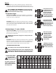
1. Use a 9/64" or 3.5 mm hex driver to loosen the screw
several turns. Do not remove it completely.
2. Slide the right end of the cover under the loosened
screw.
3. Insert the left end tabs into the last row of ventilation
slots, and slide the panel fully to the right. It should
lock into the slots.
4. Confirm that the LED's are visible through the cover.
Tighten the hex screw carefully.
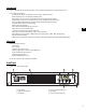
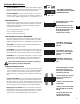
Gain controls on 2-channel models.
Markings will vary depending on model.
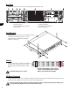
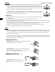
Gain controls on 4-channel models.
Markings will vary depending on model.
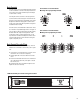
CX902 shown with gain control security plate installed.