
Instruction Manual
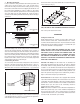
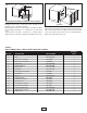


Grasp the louver housing on both sides, lift up, and pull out. This
provides access to the heating element.
N
ote: Element, limit and fan delay wiring are attached. When
removing Bezel Assembly, do so carefully as not to pull wiring
loose.
Remove dust or lint with a soft brush or a vacuum cleaner.
Replace the louver housing and tighten the Phillips head screws.
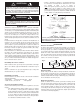
Cleaning the Fan and Motor
Remove the protective grille from the rear of the heater. This pro-
vides access to the fan and motor. Wipe off the fan and motor with
a soft cloth or brush. The fan motor does not require lubrication.
Replace protective grille (See Fig. 9).
qlyElyoExzâzá
É
ázâpnâtépErátww
Fig. 9
5
s
pl âtyrEpwpxpyâ
Heating Element Bezel Assembly & Louver Housing
Fig. 8
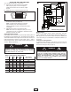
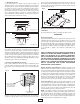
TABLE 2.
REPLACEMENT PARTS FOR UH SERIES ELECTRIC HEATERS
QUANTITY
KEY NO. DESCRIPTION PART NUMBER UH724
1 Element 302006810 1
2 Motor 3900-2008-000 1
3 Fan Control Assembly 410148000 1
4 High Temp. Limit Control 410027000 1
5 Thermostat 5813-2050-000 1
6 Thermostat Knob 3301-2014-006 1
7 Motor Mount 1215-2235-003 1
8 Fan Blade 1210-2017-000 1
9 Ceiling Bracket (Handle) 310876001 1
10 Wire Guard 312056802 1
11 Louver 3503-2004-010 4
12 Bezel Assembly 200162902 1
13 Cover (Access Door) 310104902 1
14 Bracket Screw 400029008 2
15 Cover Wrap Assembly 200193902 1
16 Control Box Assembly 200161902 1
17 Power Terminal Block 5823-0004-005 1
18 Wattage Change Board 5823-0003-001 1
19 Power Relay 5018-0004-102 1