
Instruction Manual
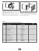


ADJUSTING AIR FLOW DIRECTION
You can adjust the direction of air flow by:
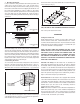
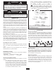
A. Turning the unit. If the unit has been installed
with a single lag bolt, as shown in Figure 6,
simply turn the entire unit as needed to adjust
air flow.
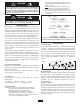
B. Tilting the unit. Loosen the bracket screws, tilt
the heater to the desired position, and re-tighten
the bracket screws (see Figure 4).
NOTE: To tilt the heater it must be mounted in
bottom keyhole slots of mounting bracket to
maintain adequate clearance and prevent possible
overheating.
C. Adjusting the louvers to the desired position.
NOTE: The louvers are designed so they can not be
completely closed. Do not attempt to defeat this feature,
damage to the unit can result.
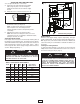
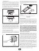
ADJUSTING HEAT OUTPUT
Heat output can be increased or decreased by switching wires at
the wattage change terminal board. The heater is factory wired to
deliver the maximum heat output for the model used. Should your
particular application require less heat output, refer to Table 1
and change the wires at the wattage change terminal board as
shown in Wiring Diagram Fig. 7.
MAINTENANCE
Because of its rugged design, superior engineering, and high-
quality craftsmanship, the UH heater requires little maintenance.
With proper care, your electric heater should last a lifetime, but
seasonal cleaning is recommended to maintain the efficiency of
the heater.
Cleaning the Heating Element
To clean the heating element, loosen (but do not remove) the four
Phillips head screws located behind the louvers in the corners of
the louver housing (See Fig. 8, page 5).
TO PREVENT POSSIBLE ELECTRIC SHOCK, DIS-
CONNECT POWER TO THE HEATER AT THE MAIN
SERVICE BOX BEFORE ATTEMPTING TO ADJUST
THE HEAT OUTPUT OF THIS UNIT.
Fig. 6
USE CARE TO PREVENT DAMAGE TO INTERNAL
HEATER WIRING WHEN CLEANING ELEMENT. MAKE
SURE ALL CONNECTIONS REMAIN TIGHT AND ALL
WIRING IS ROUTED AWAY FROM ELEMENT FINS
WHEN REASSEMBLING THE UNIT. ALLOWING
WIRING TO TOUCH THE ELEMENT FINS COULD
RESULT IN A FIRE HAZARD.
4
!
!
WARNING
WARNING
TABLE 1. HEAT OUTPUT ADJUSTMENTS
BTU/HR VOLTS WATTS
MAX
FUSE
SIZE
HEATER
AMPS
MOVE JUMPERS
FROM C-D TO A-B
25,598
240 7500
45
31.3 NONE
21,331
240 6250 35 26.1
BLUE
17,065 240 5000 30 20.9 BLUE & YELLOW
12,799 240 3750
20
15.7
BLUE, YELLOW & RED
19,198
208 5625 40 27.1
NONE
15,990
208 4685
30 22.3 BLUE
12,799
208 3750
25 18.1 BLUE & YELLOW
9,598 208 2812 20 13.6 BLUE, YELLOW & RED
G
ND
4
6
5
2
3
1
MOTOR
FAN
2
1
1
1
1
2
9
10
8
7
L1 L2
DCBA
ELEMENT
FA N
C
ONTROL
HI LIMIT
FIELD WIRING
POWER
T
ERMINAL
BLOCK
THERMOSTAT
WAT TAGE CHANGE
TERMINAL BOARD
R
ED
YEL
BLU
BLK
T3 T2 T1
CONTACTOR
L3
2
L2
1
L1
F
ig. 7
UH724ST Wiring Diagram