
Installation Guide

2
NOTE: It is recommended that no more than one thermostat be
used in each room (area).
INSTALLATION
1. The thermostat can be installed in either end of the heater
that the power wiring is brought into.
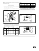
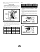
2. Remove selected junction box end cap (Figure 1) and dis-
card; save screw.
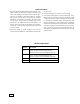
3. If the thermostat is controlling more than one heater, the total
of all heater amperage ratings (Table 1) cannot exceed 25
amps at 120 volts A.C. thru 277 volts A.C. Refer to Table 2 for
correct wire, circuit breaker, or fuse sizing.
Table 1
Model Amps Model Amps
500 4.17 1250 10.42
508 2.40 1258 6.01
504 2.08 1254 5.21
507 1.81 1257 4.51
750 6.25 1500 12.50
758 3.61 1508 7.21
754 3.13 1504 6.25
757 2.71 1507 5.42
1000 8.33 2008 9.62
1008 4.81 2004 8.33
1004 4.17 2007 7.22
1007 3.61
Table 2
Minimum AWG Circuit
Wire Size Breaker or
Total Amps (Copper) Fuse Size
0 thru 12 #14 15 Amp
12.1 thru 16 #12 20 Amp
16.1 thru 24 #10 30 Amp
4. Connect thermostat to baseboard heater and power wiring
per wiring diagram using properly sized listed wire nuts.
5. Fold wires back into wiring compartment and install the ther-
mostat assembly in place of the discarded junction box end
cap. Reuse the screw to hold the end cap in place.
6. Reconnect power at main fuse or circuit breaker distribution
panel.
*Single line break thermostats DO NOT have an “OFF” position and will
operate at a temperature below its minimum set point.
JUNCTION BOX
JUNCTION
BOX END
CAP
SCREW
HEATER
Figure 1. Removal of End Cap
BREAKS IN THE OFF POSITION
AND ON TEMPERATURE RISE
HEATER
RED
GROUND
ADDITIONAL
HEATER(S)
L1
L2
BLK
RED
BLK
CAUTION: DO NOT EXCEED
AMPERAGE RATING OF
THERMOSTAT WHEN ADDING
HEATERS.
BREAKS IN THE
OFF POSITION
ONLY
BREAKS ON TEMPERATURE
RISE ONLY*
HEATER
RED
BLACK OR WHITE
GROUND
ADDITIONAL
HEATER(S)
L1
L2
BLK
CAUTION: DO NOT EXCEED
AMPERAGE RATING OF
THERMOSTAT WHEN ADDING
HEATERS.
1 POLE
2 POLE