
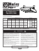
Owner's manual


Conduit, conduit connectors, and fasteners to secure heater
to ceiling are supplied by others in the following instructions.
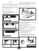
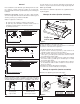
1.On a workbench or other flat surface, attach mounting
brackets to ends of wireway cover (see Figure 4A) using
bolts, star washers, and nuts supplied.
2. Remove screws (see Figure 4) from front of wireway
cover, rotate wireway cover back, and remove from wire-
way base.
3.Mount wireway cover/mounting brackets to ceiling and
secure using fasteners (by others) sized to sufficiently
support heater and any optional accessories used.
4.Remove knockout from top or either end of wireway cover
and install conduit connector and conduit.
5. Route supply wire to heater.
6. Align "T" tabs on wireway base with slots in wireway cover
and hang heater assembly on wireway cover. Allow to
hang open.
7. Proceed to wiring section (see Figure 6).
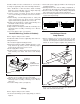
Conduit Mounting (Indoor or Outdoor)
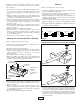
Refer to Figure 5 and proceed as follows.
Conduit and conduit connectors supplied by others in the fol-
lowing instructions.
1.Do not attach supplied mounting brackets.
2.Mount field supplied conduit to building structure, secure
using fasteners (by others) sized to sufficiently support
heater and any optional accessories used.
3.Route supply wire to heater.
4.Remove screws (see Figure 5) from front of wireway cover,
rotate wireway cover back, and remove from wireway
base.
5.Remove knockout from top of wireway cover and attach
wireway cover to conduit connector and conduit.
6.Align "T" tabs on wireway base with slots in wireway cover
and hang heater assembly on wireway cover. Allow to
hang open.
7.Proceed to wiring section (see Figure 6).
Wiring
Refer to Figure 6 and proceed as follows.
1.Connect heater wiring to power supply wiring as shown in
Figure 6.
2.Connect the power supply ground wire to the heater green
grounding lead wire.
3.Carefully fold the wires into the wiring compartment so
they will not be pinched by the wiring compartment cover.
4.Pivot the heater assembly until the wiring compartment
base rotates into place in the wiring compartment.
5.Secure the wiring compartment cover to the base with the
screws removed previously.
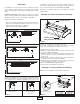
Installation of Quartz
Lamp Element
1.Remove terminal cover at each end of fixture to gain
access to terminal blocks. Loosen #10 hex nuts on termi-
nal studs. Then wrap element leads around terminals one
full turn as shown in Figure7. Tighten nuts, making sure
there is some slack in the lead after the attachment is
made. Cut off and discard extra wire.
3
screws for wiring
Remove
Wireway cover
Conduit &
Connector
1/4 (Min)
Solid Steel Rod
Typical 4 Places
Figure 5
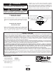
1 2
4
6
5
3
SUPPLY POWER
ELEMENT 1
ELEMENT 2
ELEMENT 3
SINGLE PHASE
1 2
4
6
5
3
SUPPLY POWER
ELEMENT 1
ELEMENT 2
ELEMENT 3
THREE PHASE
Figure 7
Figure 8
Figure 6