
User guide

© 2011 Cisco Systems, Inc. All rights reserved. This document is Cisco Public Information. Cisco Validated Design Page 71
●
PVS injects a Security Identifier (SID) and host name as each desktop boots to make them unique in AD.
These object mappings are maintained and managed within the PVS server and are visible in the PVS
Console under ―Collections‖ view are initially created and mapped by the XenDesktop Setup tool.
Note: Using CIFS to host the vDisk is not recommended by Citrix; although a ―Read Only‖ ISCSI target mode can now be used
and managed with PVS 5.8, for testing a copy of the vDisk was hosted and maintained on each PVS server‘s local disk to
provide high availability and load balancing by all servers within the farm. As the PVS servers are assigned with 8GB RAM the
image will remain persistent and be serviced by RAM after it is initially served for the first time by each server.
PVS servers can be configured in a farm to provide high availability and resilience; connections are automatically
failed over to a working server/s within the farm in the event of a failure without interruption to the desktop.
Each virtual desktop is assigned a ―Write Cache‖ (temporary file) where any delta changes (writes) to the default
image are recorded and is used by the virtual windows operating system throughout its working life cycle. This is
where ALL write I/O is conducted for the given virtual desktop instance, it is therefore important to consider where
the Write Cache is placed when scaling virtual desktops using PVS server. There are several options as to where
the Write Cache can be placed:
●
PVS Server
●
Hypervisor RAM
●
Device Local Disk (an additional Virtual Disk for VDI instances)
For optimal performance and scalability the ―Cache on devices HD‖ option is used, a 3GB virtual disk is assigned
to the virtual machine templates used in the clone creation process (described in section 5.7). By creating the
3GB drives associated with the templates on NFS volumes, mounted on the hypervisors; we are then able to
create VDI instances each with its own 3GB drive where the PVS Write Cache will be placed. In addition the PVS
Target device agent installed in the Windows 7 image will also automatically place the Windows swap file on the
same drive when this mode is enabled.
Therefore both the PVS Write Cache and Windows Swap file is now hosted on an NFS mounted volumes hosted
on NetApp storage. To further increase scalability load balancing across multiple Volumes and storage
Controllers was done by using 4 virtual machine templates (each created on different data stores/storage
repositories) and running the XenDesktop Setup Wizard tool 4 times using a different virtual machine template for
each process.
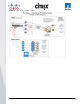
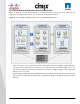
Figure 37 below illustrates Multiple virtual machine instances hosted on a hypervisor server booting from a PVS
single master image, each one has a virtual disk hosted on different NetApp provided NFS volumes where the
PVS cache is placed. This helps ensure that all write I/O takes place on the NetApp storage over NFS using high
performance storage.