Reference Architecture-Based Design Citrix XenDesktop Built on FlexPod Citrix XenDesktop Using Citrix XenServer, Cisco Unified Computing System, Nexus 5000, and NetApp Storage Cisco Validated Design July 2011
Contents 1.0 Goal ........................................................................................................................................................ 5 1.1 Audience ............................................................................................................................................. 5 1.2 Objectives ........................................................................................................................................... 5 2.
.5 FlexPod Technical Overview ............................................................................................................ 38 3.5.1 Audience.................................................................................................................................... 39 3.5.2 FlexPod Architecture ................................................................................................................. 39 3.5.3 FlexPod Market Overview .............................................
5.7.1 Cisco UCS Configuration for Citrix XenServer Installation ....................................................... 97 5.7.2 VLAN Configuration for XenServer Host Management Interfaces ............................................ 98 5.8 OS Installation .................................................................................................................................. 98 5.8.1 XenServer Networking ..............................................................................................
1.0 Goal The goal of this document is to provide architectural design and sizing guidelines for the hosting of small-to-large scale Citrix XenDesktop 4 and Citrix XenApp environments in a Cisco Data Center Fabric environment. This document presents one of a portfolio of design documents intended to simplify, ease and accelerate the deployment of Cisco VXI Desktop Virtualization Solutions.
2.0 Summary of Main Findings The hosting of Citrix XenDesktop Hosted Virtual Desktops (VDI) and Hosted Shared Virtual Desktops models and FlexCast with Citrix XenServer Hypervisors on Cisco UCS B-Series Blade Servers and NetApp storage were successfully validated. The Cisco UCS B250 M2 Extended Memory Blade Servers offer an optimal memory configuration that allows virtual desktop hosting servers to use the full CPU capabilities of the servers.
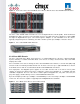
3.0 Infrastructure Components The following sections detail the infrastructure components used in this configuration. 3.1 Cisco Unified Computing System The Cisco Unified Computing System is a next-generation data center platform that unites compute, network, storage access, and virtualization into a cohesive system designed to reduce total cost of ownership (TCO) and increase business agility.
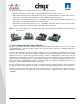
Figure 1. Cisco Unified Computing System 3.2 Cisco Unified Computing System Components 3.2.1 Fabric Interconnect The Cisco UCS 6100 Series Fabric Interconnects are a core part of the Cisco Unified Computing System, providing both network connectivity and management capabilities for the system (Figure 2). The Cisco UCS 6100 Series offers line-rate, low-latency, lossless 10 Gigabit Ethernet and FCoE functions.
The Cisco UCS 6100 Series is equipped to support the following module options: ● Ethernet module that provides 6 ports of 10 Gigabit Ethernet using the SFP+ interface ● Fibre Channel plus Ethernet module that provides 4 ports of 10 Gigabit Ethernet using the SFP+ interface; and 4 ports of 1/2/4-Gbps native Fibre Channel connectivity using the SFP interface ● Fibre Channel module that provides 8 ports of 1/2/4-Gbps native Fibre Channel using the SFP interface for transparent connectivity with existing F
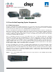
Figure 4. Rear view of Cisco UCS 5108 Blade Server Chassis with two Cisco UCS 2104XP Fabric Extenders The Cisco UCS 2104XP Fabric Extender has four 10 Gigabit Ethernet, FCoE-capable, Small Form-Factor Pluggable Plus (SFP+) ports that connect the blade chassis to the fabric interconnect. Each Cisco UCS 2104XP has eight 10 Gigabit Ethernet ports connected through the midplane to each half-width slot in the chassis.
3.2.4 Cisco UCS B200 M1 Blade Server The Cisco UCS B200 M1 Blade Server is a half-width, two-socket blade server. The system uses two Intel Xeon 5500 Series Processors, up to 96 GB of DDR3 memory, two optional hot-swappable small form factor (SFF) serial attached SCSI (SAS) disk drives, and a single mezzanine connector for up to 20 Gbps of I/O throughput. The server balances simplicity, performance, and density for production-level virtualization and other mainstream data center workloads. Figure 7.
Figure 9. Intel Xeon 5500 Series Processor 3.2.7 Intel Xeon 5600 Series Processor As data centers reach the upper limits of their power and cooling capacity, efficiency has become the focus of extending the life of existing data centers and designing new ones. As part of these efforts, IT needs to refresh existing infrastructure with standard enterprise servers that deliver more performance and scalability, more efficiently.
offer an unprecedented opportunity to dramatically advance the efficiency of IT infrastructure and provide unmatched business capabilities. Figure 10. Intel Xeon 5600 Series Processor 3.2.8 Cisco UCS B200 M2 Blade Server The Cisco UCS B200 M2 Blade Server is a half-width, two-socket blade server.
Figure 12. Cisco UCS B250 M2 Extended Memory Blade Server 3.2.10 Cisco UCS B440 M1 High-Performance Blade Server The Cisco UCS B440 M1 High-Performance Blade Server is a full-width, 4-socket system. Two or four Intel Xeon 7500 Series Processors with intelligent performance that automatically adapts to the diverse needs of a virtualized environment and offers advanced reliability for mission-critical workloads.
The Cisco UCS M71KR-Q provides both 10 Gigabit Ethernet and 4-Gbps Fibre Channel functions using drivers from QLogic, providing: ● Risk mitigation through compatibility with current QLogic adapter-based SAN environments and drivers ● Reduced TCO through consolidation of LAN and SAN traffic over the same mezzanine card and fabric, reducing the overall number of network interface cards (NICs), HBAs, cables, and switches ● Integrated management with Cisco UCS Manager Figure 15.
utilization can improve because of fewer disk waits on page-in and other I/O operations, making more effective use of capital investments and more conservative use of energy. ● For environments that need significant amounts of main memory but which do not need a full 384 GB, smaller-sized DIMMs can be used in place of 8-GB DIMMs, with resulting cost savings: two 4-GB DIMMS are typically less expensive than one 8-GB DIMM. Figure 16. Cisco Extended Memory Architecture 3.2.
3.3 Citrix XenDesktop Citrix XenDesktop is a desktop virtualization solution that delivers Windows desktops as an on-demand service to any user, anywhere. With FlexCast™ delivery technology, XenDesktop can quickly and securely deliver individual applications or complete desktops to the entire enterprise, whether they are task workers, knowledge workers or mobile workers. Users now have the flexibility to access their desktop on any device, anytime, with a highdefinition user experience.
management and automation capabilities designed to help customers create a virtual computing center, simply upgrade to one of the enhanced versions of XenServer. 3.3.3 High-Definition User Experience (HDX)Technology Citrix has been perfecting the virtual application delivery technology for more than two decades.
Figure 18. Citrix XenDesktop on XenServer Architecture ● Web Interface: Web Interface provides the user interface to the XenDesktop environment. Web Interface brokers user authentication, enumerates the available desktops and, upon launch, delivers an .ica file to the Citrix Receiver on the user‘s local device to initiate a connection. Because Web Interface is a critical component, redundant servers must be available to provide fault tolerance.
farm master server. The farm master is able to focus on its role of managing the farm when an additional XenDesktop Controller acts as a dedicated XML server. The XML server is responsible for user authentication, resource enumeration and desktop launching process. A failure in the XML broker service will result in users being unable to start their desktops.
Figure 19. Operational Sequence 1. The end user launches an internet browser to access Web Interface. 2. Web Interfaces prompts the user for Active Directory credentials and passes the credentials to the Desktop Delivery Controller acting as a dedicated XML server. 3. The XML Service running the dedicated XML server (Desktop Delivery Controller) authenticates the user against Active Directory. 4.
9. The Desktop Delivery Controller validates the login credentials and checks out a license from the Citrix License Server. If the credentials are valid and a license is available, then the credentials, XenDesktop license and policies are sent to the virtual desktop for processing. 10. Once the connection has been approved, the Virtual Desktop Agent uses the transferred credentials to logon against Active Directory and applies profile configurations. 3.3.
responsible for delivering desktops or applications, to a dedicated server. If the primary data collector were to fail, a backup, with the same hardware and software configuration, should also be available. Similar to Web Interface, providing fault tolerance to the Data Collector servers is recommended.
3.3.6 Citrix XenDesktop Hosted Shared Desktops Figure 21 details the Citrix XenDesktop Hosted Shared Desktops architecture. Figure 21. Citrix XenDesktop Hosted Shared Desktop on XenApp Architecture Citrix XenApp Farm Active Directory Data Store XML Broker/ Zone Data Collector Web Interface Citrix License Server Citrix XenApp Servers Hosted Shared Desktops 1. The end user launches a browser and enters the URL of the Web Interface site. 2.
8. The Web Interface server passes the connection information for the assigned XenApp server to the client device in the form of an ICA file. The client device automatically launches the ICA file and connects directly to the desktop of the XenApp server where the Desktop Experience Feature of Windows 2008 R2 is enabled. 9. Before opening the Desktop, the XenApp Server checks out a license from the Citrix License Server on the client‘s behalf. The client is then connected to the desktop of the XenApp server.
The follow statements describe the eight strategic features of XenDesktop 4: ● Any device, anytime, anywhere. Today‘s digital workforce demands the flexibility to work from anywhere at any time using any device they‘d like. Using Citrix Receiver as a lightweight universal client, XenDesktop users can access their desktop and corporate applications from any PC, Mac, thin client or smartphone. This enables complete workplace flexibility, business continuity and user mobility. ● HDX™ user experience.
and reporting enables rapid problem resolution, while of intelligent load and capacity management help ensure that problems never arise in the first place. Built-in virtualization management features such as live migration, high availability and bare-metal server provisioning make the infrastructure robust and resilient. The Cisco Desktop Virtualization Solution with Citrix XenDesktop delivers desktops and applications as an ondemand service to users anywhere, at any time, and on their choice of devices.
sum of the storage required by each virtual machine. For example, if each virtual machine is 20 GB in size and there are supposed to be 1000 virtual machines in the solution, it would require at least 20 B usable data on the shared storage. Thin provisioning, data deduplication, and FlexClone® are the critical components of the NetApp solution and offer multiple levels of storage efficiency across the virtual desktop OS data, installed applications, and user data.
3.4.4 NetApp Deduplication NetApp deduplication saves space on primary storage by removing redundant copies of blocks within a volume hosting hundreds of virtual desktops. This process is transparent to the application and user and can be enabled and disabled on the fly. In a Citrix XenDesktop environment, deduplication provides significant space savings, given that each virtual machine is an identical copy of the OS, applications, and patches.
For more information on deduplication, refer to NetApp TR-3505: NetApp Deduplication for FAS, Deployment and Implementation Guide 3.4.5 Performance Virtual desktops can be both read and write intensive at different times during the lifecycle of the desktop, depending on the user activity and the desktop maintenance cycle.
addition to the environmental benefits of heating and cooling, you can save 3U of rack space per shelf. For a real-world deployment, a NetApp solution (with Flash Cache as a primary component) would typically replace several such storage shelves; therefore, the savings could be considerably higher. 3.4.7 NetApp Flash Cache and PAM NetApp Flash Cache and PAM are hardware devices that extend the native Data ONTAP TSCS capabilities.
Figure 27. Citrix StorageLink 3.4.11 NetApp Operations Manager NetApp Operations Manager provides a comprehensive monitoring and management solution for the Citrix XenDesktop infrastructure. It provides comprehensive reports of utilization and trends for capacity planning and space usage. It also monitors system performance, storage capacity, and health to resolve potential problems. For more information about NetApp Operations Manager, visit http://www.netapp.
Figure 28. NetApp Operations Manager 3.4.12 Data Protection The availability of thousands of virtual desktops is dependent on the availability of the shared storage on which the virtual desktops are hosted. Thus, using the proper RAID technology is very critical. Also, being able to protect the virtual desktop images and/or user data is very important.
StorageLink Platinum Edition (starting with version 2.0) provides Site Recovery, which provides a framework for replicating and switching over a StorageLink-managed deployment of application storage resources, physical hosts, and virtual machines to another location. Site Recovery enables organizations to implement fully automated disaster recovery plans for fast, reliable site recovery of critical virtual infrastructure.
● Total number of virtual machines for which the system has to be designed (for example, 2000 virtual machines). ● The types and percentage of different types of desktops being deployed. For example, if Citrix XenDesktop is used, different desktop delivery models might require special storage considerations. ● Size per virtual machine (for example, 20GB C: drive, 2GB data disk). ● Virtual machine OS (for example, Windows XP, Windows 7, and so on).
requirements to the NetApp SE and obtain appropriate storage system configuration. If required, NetApp can help you in each phase of the process discussed above. NetApp has detailed sizing tools specific to Citrix XenDesktop that can help architect Citrix XenDesktop deployments of any scale. The tools are designed to factor in all the NetApp storage efficiency and performance acceleration components discussed earlier.
resiliency. It provides protection against double disk failure as compared to RAID 5, which can only protect against one disk failure. NetApp strongly recommends using RAID-DP on all RAID groups that store Citrix XenDesktop data. For more information on RAID-DP, refer to NetApp white paper 3298 at http://www.netapp.com/us/library/white-papers/wp_3298.html. ● Remote LAN management (RLM) card.
both the speed in which the desktops are available to the customer and overall customer experience. A ―virus scan storm‖ is similar to a boot storm in I/O but might last longer and can significantly affect customer experience. Due to these factors, it is important to make sure that the storage is architected in such a way as to eliminate or decrease the effect of these events. ● Aggregate sizing.
Cisco, NetApp, and VMware have developed FlexPod for VMware® as a platform that can address current virtualization needs and simplify their evolution to an IT as a service (ITaaS) infrastructure. FlexPod for VMware is built on the FlexPod infrastructure stack with added VMware components, including VMware vSphere™ and vCenter™ for virtualized application workloads. 3.5.
● Three chassis of Cisco UCS blades with two fabric extenders per chassis Storage is provided by a NetApp FAS3210CC (HA configuration within a single chassis) with accompanying disk shelves. All systems and fabric links feature redundancy, providing for end-to-end high availability (HA). While this is the default base design, each of the components can be scaled flexibly to support the specific business requirements in question.
Table 1. FlexPod Facilitates a Variety of Virtualized, Cloud Environments 3.5.3.3 NetApp: Unified Architecture for Extreme Efficiencies Traditional storage solutions for virtualized infrastructures force you to buy separate systems to accommodate different storage needs. NetApp‘s multiprotocol unified architecture reduces cost and complexity by meeting all of your storage requirements with a single, highly scalable solution.
3.6.2 Cisco Nexus 5500 Series Feature Highlights 3.6.2.1 Features and Benefits The switch family's rich feature set makes the series ideal for rack-level, access-layer applications. It protects investments in data center racks with standards based Ethernet and FCoE features that allow IT departments to consolidate networks based on their own requirements and timing.
3.7.1 Microsoft Windows 7 Image Creation and Provisioning The Microsoft Windows 7 image and additional Software was initially installed and prepared as a standard Virtual Machine on Citrix XenServer 5.6; prior to each one being converted into separate Citrix Provisioning server vDisk images and then 100‘s of V clones being created using the XenDesktop setup wizard tool.
3.7.1.1 Create Windows 7 Virtual Machine and Install Standard Software The following virtual machine configurations and software were used to create the initial Windows 7 virtual machine on the hypervisor which is then later extracted to create a Citrix Provisioning server vDisk image in .vhd format.
3.7.1.3 Provisioning Services (PVS) vDisk Creation Once the Windows 7 image has initially been created with the required software, it must be extracted into a Provisioning Server vDisk image. To do this, the Citrix XenConvert 2.1 tool is used which, is part of the PVS Target Device installation. To create a PVS vDisk: 1. Using the PVS Console (Must use the console from the PVS server) 2. Create new vDisk (16GB) (this may vary depending on requirements). 3. Using Diskpart set the partition offset to 1024.
Set device to boot from hard disk 6. Boot Windows 7 virtual machine and check vDisk is attached. To clone Windows 7 Image to vDisk: 1. To retain the 1024 partition offset in the vDisk the following needs to be added to the C:\Program Files\Citrix\XenConvert.ini: [parameters] PartitionOffsetBase=1048576 2. Run XenConvert 3. Run PVS Device Optimization Tool by clicking the Optimize button. 4. Image to assigned vDisk (E:\). 5. Once the Imaging process has completed shutdown the virtual machine.
2. Using Virtual Center or XenCenter start the virtual machine. 3. Add the host to the domain. 4. Restart Guest OS. 3.7.1.4 Install and Configure Additional Software Components The following software is installed post vDisk cloning: ● Citrix XenDesktop VDA 4.0.5010 ● Login VSI 2.1 and STAT Agent (tools used for benchmarking) ● SQL 2K8 Native Client (for STAT agent) 3.7.1.5 Add 3-GB Write Cache .
Next, the virtual machine templates must be created on the relevant NFS data stores hosted on the NetApp storage. If large numbers of clones are to be created, it is advisable to mount several NFS volumes to the hypervisors balanced between at least 2 NetApp storage controllers. Once the NFS Volumes have been mounted on the hypervisors, using the XenCenter client create a Windows virtual machine but do not start it. To create a new Windows 7 virtual machine (Win7_PVS_Temp): 1. Allocate 1.5 GB RAM. 2.
4. Select the vDisk. 5. Assign Virtual Desktop numbers and Host names. 6. Select desired Organization Unit where machines will be created in AD. 7. Assign Desktops to (existing) Desktop Delivery Controller Group (Group has to be created the first time tool is run). 8.
4.0 Architecture and Design of Citrix XenDesktops on Cisco Unified Computing System and NetApp Storage 4.1 Design Fundamentals There are many reasons for considering a virtual desktop solution such as; an ever growing and diverse base of user devices, complexity in management of traditional desktops, security, and even Bring Your Own Computer (BYOC) to work programs.
For the purposes of the validation represented in this document, the following two virtual desktop were validated. Each of the sections provides fundamental design decisions for each respective environment. The aforementioned hosted, server-based desktop is referred to as Hosted Shared, and the hosted virtual desktop as Hosted VDI. 4.1.1 Hosted Shared Design Fundamentals Citrix XenApp 6 can be used to virtualize both desktops and applications.
4.1.2.1 Hypervisor Selection Citrix XenDesktop is hypervisor agnostic, so any of the following hypervisors can be used to hosted VDI-based desktops: ● XenServer Citrix® XenServer® is a complete, managed server virtualization platform built on the powerful Xen® hypervisor. Xen technology is widely acknowledged as the fastest and most secure virtualization software in the industry.
● Difference Disk Mode: Difference Cache is in a file on the server, or on a share, SAN, or other. The Cache file size grows as needed, but never gets larger than the original vDisk, and frequently not larger than the free space on the original vDisk. It is slower than RAM cache and Server Cache. 4.1.3 Designing a Citrix XenDesktop Deployment For detailed information about configurations, architecture, and design recommendations for delivering virtual desktops with XenDesktop, refer to http://support.
5.0 Solution Validation This section details the configuration and tuning that was done to various components for a complete solution validation. 5.1 Configuration Topology for Scalability of Citrix XenDesktops on Cisco Unified System and NetApp Storage Figure 31 shows the configuration architecture. Figure 32. Architecture Block diagram Figure 32 above captures the architecture diagram for purpose of this study.
Figure 33. Detailed Architectural of the Configuration © 2011 Cisco Systems, Inc. All rights reserved. This document is Cisco Public Information.
5.2 Cisco Unified Computing System Configuration This section details the Cisco Unified Computing System configuration that was done as part of the infrastructure build out. The racking, power and installation of the chassis are described in the install guide (refer to http://www.cisco.com/en/US/docs/unified_computing/ucs/hw/chassis/install/ucs5108_install.html) and it is beyond the scope of this document.
chassis. The Fabric interconnect is configured in End Host Mode. 5 Configure and enable upstream Ethernet links and Fibre Channel links. 6 When the blades are discovered, it is time to set the KVM IP addresses for each of the blades. This is done through the admin tab communication management Management IP address pool. One has to make sure we have ample IP address for all the blades and make sure the gateway and netmask is set correctly. © 2011 Cisco Systems, Inc. All rights reserved.
7 7.1 Create all the pools: MAC pool, WWPN pool, WWNN pool, UUID pool, Server pool MAC pool 7.2 WWPN pool 7.3 WWNN pool © 2011 Cisco Systems, Inc. All rights reserved. This document is Cisco Public Information.
7.4 UUID pool 7.5 Server pool © 2011 Cisco Systems, Inc. All rights reserved. This document is Cisco Public Information.
8 Create vHBA template 9 Create vNIC template © 2011 Cisco Systems, Inc. All rights reserved. This document is Cisco Public Information.
10 11 12 Create boot from SAN policies, adapter policies, Create a service profile template using the pools, templates, and policies configured above. After associating a server pool to the service profile template, just right click to deploy as many service profile as you need and Cisco UCS Manager will automatically start configuring these new service profile templates on the selected blade servers.
3. Now add this as a policy to the template: This will reboot the servers and when the servers come back up the memory DIMMs will be in 1333MHz. © 2011 Cisco Systems, Inc. All rights reserved. This document is Cisco Public Information.
5.2.1 QOS and COS in Cisco Unified Computing System Cisco Unified Computing System provides different system classes of service to implement quality of service including: ● System classes that specify the global configuration for certain types of traffic across the entire system ● QoS policies that assign system classes for individual vNICs ● Flow control policies that determine how uplink Ethernet ports handle pause frames.
Class to CoS Map by default in Cisco Unified Computing System Cisco UCS Class Names Cisco UCS Default Class Value Best effort Match any Fc 3 Platinum 5 Gold 4 Silver 2 Bronze 1 Default Weight in Cisco Unified Computing System Cisco UCS Class Names Best effort Fc Weight 5 5 The following are the steps to enable QOS on the Cisco Unified Computing System: 1. Configure platinum policy by checking the Platinum policy box and if you want jumbo frames enabled change MTU from normal to 9000.
3. Include this policy into the vNIC template under the QoS policy. This is a unique value proposition of the Cisco Unified Computing System with respect to end-to-end QOS. For example, you could have a VLAN for the NetApp storage and configure Platinum policy and Jumbo frames and get an end-to-end QOS and performance guarantee. You can configure the NIC to have a no-drop class along with the platinum policy. © 2011 Cisco Systems, Inc. All rights reserved. This document is Cisco Public Information.
5.3 Citrix XenDesktop Configuration Figure 34 shows the Citrix XenDesktop configuration. Figure 34.
Table 3. Citrix Provisioning Server 5.6 Citrix Provisioning Server 5.6 OS: CPU: Disk: Service Pack: Windows 2008 Enterprise R2 64bit RAM: 2 x vCPU 8192MB Network: 1 x70GB Virtual Disk 1 x 1GbE (hosted on NFS target volume on NetApp Storage) Database for PVS hosted on separate Microsoft SQL Server 2008 64bit Table 4.
5.3.1 Citrix XenDesktop Desktop Delivery Controller (DDC) The DDCs were virtualized on XenServer server and some of the roles of the DDC were assigned to specific DDCs, an approach commonly taken in Citrix XenApp deployments. The DDCs were configured such that: ● DDC 1: Farm Master and Pool Management ● DDC 2 and 3: VDA Registrations and XML Brokering In this environment, 3 DDCs (4vCPU, 4GB RAM) easily sustained the farm size of 1920 desktops and proved stable at all various stages of testing. 5.3.
● Changed the Threads per port from the default 8 to 31. This is necessary when streaming to high amounts of target devices. ● Configured the bootstrap file to contain the static IP address assigned to each of the provisioning servers. ● Created a local vDisk store for each of the Provisioning Servers and configured it to the D: drive. ● Copied the 25GB Windows7 vDisk to each server‘s D: drive. 5.3.
Network configuration for the XenServers hosting the virtual desktop virtual machines: ● Assigned separate NICs for mgmt and storage traffic and configured appropriate host access at NetApp to limit access to the correct VLAN.
● PVS injects a Security Identifier (SID) and host name as each desktop boots to make them unique in AD. These object mappings are maintained and managed within the PVS server and are visible in the PVS Console under ―Collections‖ view are initially created and mapped by the XenDesktop Setup tool. Note: Using CIFS to host the vDisk is not recommended by Citrix; although a ―Read Only‖ ISCSI target mode can now be used and managed with PVS 5.
Figure 37. vDisk Hosting on NFS Volumes © 2011 Cisco Systems, Inc. All rights reserved. This document is Cisco Public Information.
5.3.7 Hosted Shared Desktops Environment Configuration Figure 38 details the Hosted Shared Desktop on XenApp performance testing setup at the Cisco labs. All components including the infrastructure roles were virtualized using Citrix XenServer. Figure 38. Citrix XenApp Scalability Testing on Cisco UCS B200 M2 Blade Server ● Login VSI Launcher setup. Login VSI 2.
Figure 39. Optimization for Virtualizing Citrix XenApp on Citrix XenServer ● Cisco UCS B200 M2 Blade Server. Cisco UCS B200 M2 blade server with two Intel Xeon 5600 Series processors and 96GB of DDR3 memory was utilized for the testing. ● NetApp FAS3140 Filer. A dedicated Storage Repository over a Fibre Channel LUN on NetApp FAS3140 Filer was used for storing data for all virtualized workloads in the environment, including the Citrix XenApp virtual machines. 5.
Figure 40. Network Configuration with Upstream Cisco Nexus 5500 Series from the Cisco Unified Computing System The Cisco Nexus 5500 Series is used to connect to the NetApp FAS 3140/3170 storage system for NAS access. NetApp supports dual port 10G Chelsio cards which are configured in a portchannel and connected to the pair of Cisco Nexus 5500 Series downstream.
Figure 41. Network Configuration for NetApp NAS or Filer Storage The configuration on the NetApp storage as gathered from the filer view is shown in Figure 42. Figure 42. Network Configuration on the NetApp Storage Side © 2011 Cisco Systems, Inc. All rights reserved. This document is Cisco Public Information.
5.5 SAN Configuration A pair of Cisco Nexus 5500 series were used in the configuration to connect to the Fibre Channel port of the Cisco UCS fabric interconnect fibre channel expansion module ports to the NetApp storage Fibre Channel ports. Single initiator zone was used to connect to the NetApp Fibre Channel ports. The SAN switch was predominantly used for configuring boot from SAN of the XenServer server blades.
zone name XD-Xen-Server-2-fc0 vsan 100 * fcid 0x47002e [pwwn 20:00:00:25:b5:0a:ad:3c] * fcid 0x470200 [pwwn 50:0a:09:83:89:1a:b9:d9] * fcid 0x470300 [pwwn 50:0a:09:81:89:1a:b9:d9] Where 20:00:00:25:b5:0a:ad:3e/20:00:00:25:b5:0a:ad:2e are server‘s pwwn of the CNA that are part of the Fabric A side. Similar zoning is done on the corresponding Nexus 5500 series switch pair to take care of the Fabric B side as shown below.
Figure 43. NetApp Fibre Channel target ports 5.5.1 Boot From SAN Booting from SAN is another critical feature which helps in moving towards stateless computing in which there is no static binding between a physical server and the OS / applications it is supposed to run. The OS is installed on a SAN lun and boot from SAN policy is applied to the service profile template or the service profile.
● High Availability: A typical data center is highly redundant in nature - redundant paths, redundant disks and redundant storage controllers. When operating system images are stored on disks in the SAN, it supports high availability and eliminates the potential for mechanical failure of a local disk.
4. Now add the LUN to the initiator group © 2011 Cisco Systems, Inc. All rights reserved. This document is Cisco Public Information.
5. Make sure the add initator group succeeds 6. Now we need to mask the LUN, proceed to LUN > Manage LUN and select the new LUN which needs to be added and select the ―no map‖ section as shown below. © 2011 Cisco Systems, Inc. All rights reserved. This document is Cisco Public Information.
7. Add the group to the map 8. Select the new initiator group bootlun to add. © 2011 Cisco Systems, Inc. All rights reserved. This document is Cisco Public Information.
9. Assign a LUN ID to the initiator group 10 11 Make sure the mapping succeeded. After the LUN map is successfully updated, check to see if the Manage LUNs show a correct mapping. 12 Repeat the steps 3 through 11 for the number of servers you want to do boot from SAN. © 2011 Cisco Systems, Inc. All rights reserved. This document is Cisco Public Information.
5.5.3 SAN Configuration The fcoe and npiv feature has to be turned on in Nexus 5500 series switch. Also make sure you have 4 GB SPF+ modules connected to the Cisco UCS 61x0 XP Fabric Interconnects. The port mode is set to AUTO as well as the speed is set to AUTO. VSAN configuration has to be done either in the SAN switch CLI or in the Cisco Device Manager. Cisco Fabric Manager can also be used to get a overall picture of the SAN configuration and zoning information.
5.5.4 Cisco UCS Manager Configuration To enable boot from SAN from a Cisco UCS Manager perspective, do the following: Ste p# 1. Task description 2. Add SAN Boot for primary. The vHBA is optional, it could be left blank and we do not have to enforce the vHBA name. 3. Add SAN boot for SAN Secondary Create a boot policy in the ―Servers‖ tab. To do this, Select the policies and on the right plane select boot policies and select ―Add‖ button.
4. Now add Boot target WWPN to the SAN Primary, make sure this is exactly what the NetApp FAS 3140 pwwn. Avoid any typos and copy paste from Nexus 5500 series switch ―show flogi da‖. N5K-A# sh fcns da vsan 1 | incl Net 0x470300 N 50:0a:09:81:89:1a:b9:d9 (NetApp) scsi-fcp 0x470200 N 50:0a:09:83:89:1a:b9:d9 (NetApp) scsi-fcp N5K-B # sh fcns da vsan 1 | incl Net 0x470400 N 50:0a:09:83:99:1a:b9:d9 (NetApp) scsi-fcp 0x470500 N 50:0a:09:81:99:1a:b9:d9 (NetApp) scsi-fcp 5. 6. 7.
8. At the end your Boot from SAN policy should look like: 9. The last step is to make the association of the service profile template to the Boot from SAN policy during the service profile template configuration. One could also modify the Boot order as shown: 10. This completes the BFS configuration on Cisco UCS Manager. When the service profile is created out of the template, each server will be ready to boot from SAN provided the appropriate OS installation steps has taken place. 5.
Figure 44. NetApp Storage Configuration © 2011 Cisco Systems, Inc. All rights reserved. This document is Cisco Public Information.
5.6.1 Example of a NetApp NFS Volume Configuration Task Description # 1. Login to the NetApp storage using a web browser and click on filerView. It starts the NetApp storage configuration application. 2. Once in the FilerView select the aggregates section and click add to create an aggregate. We created an aggregate out of 46 disks and called it aggr1. 3. Now from the volumes section, select add to add a volume. An Add volume wizard pops up. © 2011 Cisco Systems, Inc. All rights reserved.
4. Select flexible volume for the volume type © 2011 Cisco Systems, Inc. All rights reserved. This document is Cisco Public Information.
5. Input volume name and language (default POSIX is fine) 6. Select the aggregate to contain this volume © 2011 Cisco Systems, Inc. All rights reserved. This document is Cisco Public Information.
7. Input the volume size and snapshot reserve 8. We are all done, press commit. © 2011 Cisco Systems, Inc. All rights reserved. This document is Cisco Public Information.
9. After the volume is added, go to the NFS section and click on manage export, and “add export” to make it available to all host. You could also do host based access control instead of all hosts and set root access. For example: © 2011 Cisco Systems, Inc. All rights reserved. This document is Cisco Public Information.
5.6.2 NetApp Deduplication in Practice As described in section 3.6.4, NetApp deduplication saves space on primary storage by removing redundant copies of blocks within a volume hosting hundreds of virtual desktops. An example is shown in Figure 45 for an 800 GB volume hosting 428 desktops each with 3 GB capacity. © 2011 Cisco Systems, Inc. All rights reserved. This document is Cisco Public Information.
Figure 45. NetApp Deduplication 5.7 Citrix XenServer Configuration This section details the XenServer configuration and any tuning that was done on for testing. The following configurations were made to the environment to capture data and increase overall performance: ● A custom XenServer performance measurement script was configured on the XenServers to gather more specific CPU data as noted in Citrix support article as per CTX124157.
As XenServer uses an inbuilt database which is shared between hosts within a resource pool, the XenCenter client can be installed and run on any windows machine and used by administrators to connect and manage them; therefore there is no requirement for a separate management server. One of the goals we set out to test in this exercise was to virtualize the entire infrastructure components including the Citrix XenDesktop management services.
5.7.2 VLAN Configuration for XenServer Host Management Interfaces Switch ports were configured to perform 802.1Q VLAN tagging/un-tagging, commonly referred to as ports with a native VLAN (or as access mode) ports. These are the only port types supported for use with XenServer management interface/s for management traffic on a desired VLAN. In this case the XenServer host is unaware of any VLAN configuration.
Once the XenServer installation starts, after initially setting the Keyboard map the following screen appears: 1. At this stage change the KVM Virtual Media so that the QLogic .iso is connected, then select ―Local Media.‖ 2. Press ―F9‖ to load additional Drivers and install the available QLogic Drivers. Note: This process is repeated at the end of the actual XenServer Installation as at this stage you are only defining a supplemental pack for the later installation of the drivers. 3.
5. To install XenServer on the SAN select any of the available ―NetApp LUN‖ drives, i.e. ―sdc – 50 GB [NETAPP LUN]‖. 6. At the end of the XenServer installation you are prompted for the QLogic driver supplemental pack; connect the QLogic .iso using the KVM Virtual Media and select OK. Following the installation screens as normal and when finished you will be prompted for any additional supplemental packs, if you have none press skip to complete the installation.
To do this for each server using the XenCenter client ,once each host is added to a resource pool and VLAN networks created: 1. Server from the list. 2. Select Network Tab. 3. Click the Configure button. 4. Enter Name – Storage. 5. Assign Network (i.e. select VLAN 166 from drop down list). 6. Enter IP and Subnet mask addresses (do not configure gateway as do not want the traffic to route to any other network). 7. Click OK.
● Storage: A single volume was used to host all the infrastructure virtual servers and mounted using the native NFS option. In addition a CIFS share was mounted so that .iso images could be attached through the virtual machine virtual CD drive during installation and configuration processes. ● VDA Pool 1 and 2(8 XenServers configured in each pool, configuration the same; each hosting 50% of desktop virtual machines).
© 2011 Cisco Systems, Inc. All rights reserved. This document is Cisco Public Information.
6.0 Test Setup and Configurations This section discusses the various test configurations. We started with the single server scalability to determine the maximum amount of desktops that can be loaded on a given server without making the user response times go more than the criteria for success along with other success criteria parameters. We then scaled the environment to two chassis and then four chassis. 6.1 Cisco UCS Test Configuration for Single-Server Scalability Test Setup Figure 47.
Software components ● Cisco UCS firmware 1.3(1i) ● XenServer 5.6 ● XenDesktop 4 ● Windows 7 – 32 bit, 1 vCPU, 1.5 GB of memory, 30 GB per virtual machine 6.2 Cisco UCS Configuration for Two-Chassis Test Figure 48. Two-Chassis Test Configuration-8 x Cisco UCS B250 Blade Server Hardware components ● 8 X Cisco UCS B250-M2 (5680 @ 3.33 GHz) blade servers with 192 GB of memory (4 GB X 48 DIMMS @ 1333 MHz) ● 2 X Cisco UCS B200-M2 (5680 @ 3.
Software components ● Cisco UCS firmware 1.3(1i) ● XenServer 5.6, XenCenter 5.6 ● XenDesktop 4 ● Windows 7 – 32 bit, 1vCPU, 1.5 GB of memory, 30 GB per virtual machine 6.3 Cisco UCS Configuration for Four-Chassis Test Figure 49. Cisco UCS Entry Bundle with Additional Scale Bundles Hardware components ● 16 X Cisco UCS B250 M2 (5680 @ 3.33 GHz) blade servers with 192 GB of memory (4 GB X 48 DIMMS @ 1333 MHz) ● 2 X Cisco UCS B200 M2 (5680 @ 3.
Software components ● Cisco UCS firmware 1.3(1i) ● XenServer 5.6, XenCenter 5.6 ● XenDesktop 4 ● Windows 7 – 32 bit, 1vCPU, 1.5 GB of memory, 30 GB per virtual machine 6.4 Testing Methodology All validation testing was conducted on-site within the Cisco labs with joint support from both Citrix and NetApp resources.
● This workload emulates a medium ―knowledge worker‖ using the Office 2007, IE and PDF applications and opens up to 5 applications simultaneously with a type rate of 160ms for each character. The workload observes approximately 2 minutes of idle time which closely simulates real-world users. ● Once a session has been started the medium workload will repeat every 12 minutes. During each loop the response time is measured every 2 minutes.
expected to be less than 2000ms in order to assume that the user interaction with the virtual desktop is at a functional level. VSI Max is reached when the response times reaches or exceeds 2000ms for 6 consecutive occurrences. If VSI Max is reached, then the test run is considered a failure given that user experience has significantly degraded.
7.0 Test Results The purpose of this testing is to provide the data needed to validate Citrix XenDesktop 4 FlexCast models Hosted VDI and Hosted Shared with Citrix XenServer 5.6 virtualizing Microsoft Windows 7 desktops on Cisco UCS blade servers using a NetApp FAS 3140 storage array. The test results are divided into the individual FlexCast models Hosted VDI and Hosted Shared.
Figure 50. 110 Desktop Sessions on XenServer Below 2000ms 7.1.2 Two Cisco UCS Blade Chassis Validation The two Cisco UCS blade chassis environment contained a total of 8 blades with 192 GB of RAM per blade. The following table provides the VSI COPI score for the overall 8 Cisco UCS blade environment and shows that 100% of all the 880 virtual desktop sessions executed without issue.
Figure 51. 880 Desktop Sessions on XenServer Below 2000ms 3000 880 Desktop Sessions on XenServer Below 2000ms: 100% Average Response_Time Max Response_Time Response time / ms Min Response_Time 2000 1000 1 31 61 91 121 151 181 211 241 271 301 331 361 391 421 451 481 511 541 571 601 631 661 691 721 751 781 811 841 871 901 931 0 Active Sessions 7.1.3 Four Cisco UCS Blade Chassis Validation The four Cisco UCS blade chassis environment contained a total of 16 blades with 192GB of RAM per blade.
From the graph below, it can be concluded that the user response time was not affected by the heavy 1760 desktop load given that all response times are below the 2000ms threshold. Figure 52. 1760 Desktop Sessions on XenServer Below 2000ms As previously mentioned, the following two graphs are only representative of a single Cisco UCS blade server‘s ‗average CPU utilization‘ and ‗total memory used‘ to provide a sample of the performance metrics as recorded for the overall 16-blade environment.
For the 4-chassis environment, a total of two XenServer resource pools were configured with one master and seven member servers per pool. The CPU data in the following graphs provides an additional breakdown of the CPU performance for a master server and a select member server for each of the two resource pools. © 2011 Cisco Systems, Inc. All rights reserved. This document is Cisco Public Information.
Figure 53. XenServer Resource Pool 1 – Master Figure 54. XenServer Resource Pool 1 – Member © 2011 Cisco Systems, Inc. All rights reserved. This document is Cisco Public Information.
Figure 55. XenServer Resource Pool 2 – Master Figure 56. XenServer Resource Pool 2 – Member Avg CPU across all cores 1 0.9 0.8 0.7 0.6 0.5 0.4 0.3 0.2 0.
a single XenServer. Each virtual desktop was configured with 1.5 GB of RAM. With 110 virtual desktops utilizing 1.5 GB of RAM per virtual desktop, 165GB of the available memory is consumed by virtual desktops. The variance between 165GB and the line shown on the graph is the amount of memory being utilized by the XenServer hypervisor. When assessing the overall results of the testing is that the VM per CPU core density was maintained across all test environment configurations.
Figure 57. XenServer Resource Pool 1 – Master © 2011 Cisco Systems, Inc. All rights reserved. This document is Cisco Public Information.
Figure 58. XenServer Resource Pool 1 - Member © 2011 Cisco Systems, Inc. All rights reserved. This document is Cisco Public Information.
Figure 59. XenServer Resource Pool 2 – Master © 2011 Cisco Systems, Inc. All rights reserved. This document is Cisco Public Information.
Figure 60. XenServer Resource Pool 2 – Member © 2011 Cisco Systems, Inc. All rights reserved. This document is Cisco Public Information.
7.1.3.1 Storage Data for Four-Chassis Validation Please refer to section NetApp Storage Configuration, that details the volume layout on a per controller basis to interpret the Storage results described in this section. Figure 61. Total Disk Throughput on a Controller Basis © 2011 Cisco Systems, Inc. All rights reserved. This document is Cisco Public Information.
Figure 62. Total Network Throughput on a Controller Basis © 2011 Cisco Systems, Inc. All rights reserved. This document is Cisco Public Information.
Figure 63. Total Protocol Operations Figure 64. NFSv3 Read Sizes © 2011 Cisco Systems, Inc. All rights reserved. This document is Cisco Public Information.
Figure 65. NFSV3 Write Sizes 7.2 Citrix XenDesktop with XenApp Hosted Shared Test Results Customers are looking to virtualize XenApp implementations for a combination of reasons, some which include the flexibility to consolidate under-utilized XenApp servers, application or desktop silos, business continuity planning, etc. So when looking to virtualize XenApp for Hosted Shared desktops, it is important to assess the best virtual machine configurations for optimal performance.
The following graph represents the total number of sessions per configuration as also noted in the table above. 190 180 170 Number of User Sessions 160 150 140 130 120 6vCPU*4VMs 4vCPU*6VMs 8vCPU*3VMs Citrix XenApp VM Configurations ● Optimal multiple virtual machine configuration on a single Cisco UCS B200 M2 Blade Server (maximum scale-out. The maximum number of user sessions supported on a single Cisco UCS B200 M2 Blade Server with multiple XenApp virtual machines was 180.
Total Sessions Launched 180 Uncorrected Optimal Performance Index (UOPI) 180 Stuck Session Count before UOPI(SSC) 2 Lost Session Count before UOPI (LSC) 0 Corrected Optimal Performance Index (COPI = UOPI – (SSC*50%) - LSC) 179 In addition to evaluating the successful completion of the workload within a user‘s desktop session, you must make sure that the user experience did not degrade as load was increased on the environment.
Figure 67. Citrix XenApp Virtual Machine Average CPU Utilization During Steady-State Execution of 45 User Sessions From the CPU utilization graph (above) it can be noted that the CPUs were reaching their limit with 45 user session given that the average CPU usage hovered around 85%. In regards to Memory, each XenApp virtual machine was configured with 16GB of RAM per virtual machine, so from the Total Memory Used graph below, it can be concluded that Memory was not a limiting factor.
Figure 68.
8.0 Scalability Considerations and Guidelines There are many factors to consider when you begin to scale beyond four chassis or 16 servers, which this reference architecture has successfully tested. In this section we give guidance to scale beyond four Cisco UCS chassis. 8.1 Cisco UCS System Configuration As the results indicate we are seeing linear scalability in the Cisco UCS reference architecture implementation. No. of Chassis 1 XenServer No. of B250-M2 No.
9.0 Acknowledgments Projects of this magnitude could only be done with co-operation of all the parties involved and this work is a clear testimony of that. A lot of people had helped to make this project successful, we would like to acknowledge the contribution of Purnanand for helping out in Networking configuration, Lab guys – TJ and Vincent for accommodating all requests, Lisa DeRuyter for documentation.
10.0 References TR-3747: NetApp Best Practices for File System Alignment in Virtual Environments http://media.netapp.com/documents/tr-3747.pdf Cisco Nexus 5500 Series Switch CLI Software Configuration Guide http://www.cisco.com/en/US/docs/switches/datacenter/nexus5500/sw/configuration/guide/cli_rel_4_0_1a/CLIConfi gurationGuide.html Cisco Nexus 5500 series NX-OS SAN Switching Configuration guide http://www.cisco.
APPENDIX A Cisco Nexus 5500 Network Configuration switchname N5K-A # system jumbomtu 9000 logging event link-status default class-map type qos class-platinum match cos 5 class-map type queuing class-platinum match qos-group 2 policy-map type qos system_qos_policy class class-platinum set qos-group 2 policy-map type queuing system_q_in_policy class type queuing class-platinum bandwidth percent 50 class type queuing class-fcoe bandwidth percent 20 class type queuing class-default bandwidth percent 30 policy-m
mtu 9000 multicast-optimize system qos service-policy type qos input system_qos_policy service-policy type queuing input system_q_in_policy service-policy type queuing output system_q_out_policy service-policy type network-qos system_nq_policy snmp-server user admin network-admin auth 0x6ab2f7da5f26e2b1bc37d79438a89bb3 localizedkey md5 0x6ab2f7da5f26e2b1bc37d79438a89bb3 priv vrf context management ip route 0.0.0.0/0 10.29.164.
switchport trunk native vlan 164 switchport trunk allowed vlan 121-122,164-166 spanning-tree port type edge trunk speed 10000 interface port-channel3 switchport mode trunk vpc 3 switchport trunk native vlan 164 switchport trunk allowed vlan 121-122,164-166 spanning-tree port type edge trunk speed 10000 interface port-channel4 switchport mode trunk vpc 4 switchport trunk native vlan 164 switchport trunk allowed vlan 121-122,164-166 spanning-tree port type edge speed 10000 interface port-channel5 switchpor
interface port-channel11 untagged cos 5 vpc 11 switchport access vlan 166 speed 10000 interface port-channel12 vpc 12 switchport access vlan 166 speed 10000 interface port-channel13 vpc 13 switchport access vlan 166 speed 10000 interface Ethernet1/1 switchport mode trunk switchport trunk native vlan 164 switchport trunk allowed vlan 121-122,164-166 spanning-tree port type edge trunk channel-group 4 mode active interface Ethernet1/2 switchport mode trunk switchport trunk native vlan 164 switchport trunk
interface Ethernet1/4 switchport mode trunk channel-group 1 mode active interface Ethernet1/5 switchport mode trunk switchport trunk native vlan 164 switchport trunk allowed vlan 121-122,164-166 spanning-tree port type edge trunk channel-group 5 mode active interface Ethernet1/6 switchport mode trunk switchport trunk native vlan 164 switchport trunk allowed vlan 121-122,164-166 spanning-tree port type edge trunk channel-group 5 mode active interface Ethernet1/7 switchport access vlan 166 spanning-tree po
interface Ethernet1/10 switchport access vlan 166 spanning-tree port type edge channel-group 11 interface Ethernet1/11 interface Ethernet1/12 interface Ethernet1/13 switchport mode trunk switchport trunk native vlan 164 switchport trunk allowed vlan 121-122,164-166 spanning-tree port type edge trunk channel-group 2 mode active interface Ethernet1/14 switchport mode trunk switchport trunk native vlan 164 switchport trunk allowed vlan 121-122,164-166 spanning-tree port type edge trunk channel-group 2 mode
interface Ethernet1/17 shutdown switchport trunk native vlan 164 switchport trunk allowed vlan 164-166 interface Ethernet1/18 shutdown switchport trunk native vlan 164 switchport trunk allowed vlan 122,164-166 interface Ethernet1/19 interface Ethernet1/20 switchport mode trunk switchport trunk allowed vlan 121-122,164-166 © 2011 Cisco Systems, Inc. All rights reserved. This document is Cisco Public Information.
Cisco Systems, Inc. 170 West Tasman Drive San Jose, CA 95134-1706 USA www.cisco.com Tel: 408 526-4000 800 553-NETS (6387) Fax: 408 527-0883 © 2010 Cisco Systems, Inc. All rights reserved. Cisco, the Cisco logo, and Cisco Systems are registered trademarks or trademarks of Cisco Systems, Inc. and/or its affiliates in the United States and certain other countries. All other trademarks mentioned in this document are the property of their respective owners.
About Cisco Validated Design (CVD) Program The CVD program consists of systems and solutions designed, tested, and documented to facilitate faster, more reliable, and more predictable customer deployments. For more information visit www.cisco.com/go/designzone. ALL DESIGNS, SPECIFICATIONS, STATEMENTS, INFORMATION, AND RECOMMENDATIONS (COLLECTIVELY, "DESIGNS") IN THIS MANUAL ARE PRESENTED "AS IS," WITH ALL FAULTS.