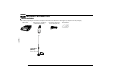
AT-598 Mobile Radiao PWR - -L VOL FCC ID:T4KAT598V HU A NN E FUNC V/M CALL MHz TX/DCS CAL SCAN MINI
3OHDVH REVHUYH WKH IROORZLQJ SUHFDXWLRQV WR SUHYHQW ¿UH SHUVRQDO LQMXU\ or transceiver damage: Do not attempt to configure your transceiver while driving, it is dangerous. This transceiver is designed for a 13.8V DC power supply. Don't use a 24V battery to power on the transceiver. Do not place the transceiver in excessively dusty, humid or wet areas, nor unstable surfaces. Please keep it away from interferential devices (such as TV, generator etc.).
CONTENTS 1HZ DQG ,QQRYDWLYH )HDWXUHV ..............................................1 Transmitting Optional Signaling ...................................................... 13 Supplied Accessories/Optional Accessories.....................2 Channel Edit .................................................................................... 13 Supplied Accessories....................................................................... 2 Channel Delete .........................................................
CONTENTS Band-width Selection ....................................................................... 20 Squelch Level .................................................................................. 27 TX OFF Setup.................................................................................. 21 Optional Signaling ........................................................................... 27 Busy Channel Lockout ..................................................................... 21 Scan Skip ..
New and Innovative Features 1 598 Mobile Radio has nice housing, stoutness & stability, advanced and reliable functions, perfect & valuable. This amateur mobile radio especially designs for drivers and it pursues company philosophy of innovation and practicality. More functions as follows: 'LVSOD\ RQ D ODUJH /&' ZLWK DGMXVWDEOH EULJKWQHVV FRQYHQLHQW IRU QLJKWWLPH XVH There are Amateur operation mode and Professional operation mode for option.
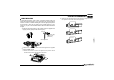
2 Supplied Accessories Supplied Accessories After carefully unpacking the transceiver, identify the items listed in the table below. We suggest you keep the box and packaging.
Initial Installation Mobile installation To install the transceiver, select a safe, convenient location inside your vehicle that minimizes danger to your passengers and yourself while the vehicle is in motion. Consider installing the unit at an appropriate position so that knees or legs will not strike it during sudden braking of your vehicle. Try to pick a well ventilated location that is shielded from direct sunlight.
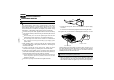
3 Initial Installation DC Power Cable Connection Red Locate the power input connector as close to the transceiver as possible. Mobile Operation The vehicle battery must have a nominal rating of 12V. Never connect the transceiver to a 24V battery. Be sure to use a 12V vehicle battery that has sufficient current capacity. If the current to the transceiver is insufficient, the display may darken during transmission, or transmitting output power may drop excessively. 1.
Initial Installation To turn on the unit, press the power switch manually while it is illuminated. (While ignition key is at ACC or ON position) 8. When the ignition key is turned to ACC or ON position with the radio's power switch on, the unit turns on automatically and the power switch will be lit. Turn the ignition key to OFF position or manually turn the power switch off to shut down the radio. 9. Using extra cable, power consumption:5MAH.
3 Initial Installation REPLACING FUSES If the fuse blows, determine the cause, then correct the problem. After the problem is resolved, replace the fuse. If newly installed fuses continue to blow, disconnect the power cable and contact your authorized mobile radio dealer or an authorized mobile radio servicecenter for assistance. ,PSRUWDQW The range of displayed voltage is only from 7V to16V DC, because the displayed value is estimated, please use a voltmeter when a more precise reading is desired.
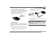
Initial Installation Accessories Connections External Speaker If you plan to use an external speaker, choose a speaker with an LPSHGDQFH RI ȍ 7KH H[WHUQDO VSHDNHU MDFN DFFHSWV D PP mono (2-conductor) plug. 3 Microphone For voice communications, connect a microphone equipped with an 8-pin modular plug into the modular socket on the front of the main XQLW 3UHVV ¿UPO\ RQ WKH SOXJ XQWLO WKH ORFNLQJ WDE FOLFNV $WWDFK WKH supplied microphone hanger in an appropriate location using the screws inc
4 Getting Acquainted Front panel Press key. FUNC key until NO. KEY VOL NA U H - EN L PWR FUNC V/M CALL MHz TX/DCS CAL SCAN MINI - 8 Main Dial FUN/SET V/M/MW MHz/SHIFT TS/DCS/LOCK CAL SQL/D Data Terminal TX Mic.
Getting Acquainted Rear panel 2 3 1 )81&7,21 Terminal for connecting optional cable QCC01 for Ext. Power use with ignition key On/Off function. The radio will auto power on when car is driving. Jack The radio will auto power off when car stops. Ext.Speaker Terminal for optional external speaker SP01 Terminal Antenna &RQQHFWLRQ IRU ȍ FRD[LDO FDEOH DQG DQWHQQD Connector NO. KEY DISPLAY 13 7 SQL M )81&7,21 Squelch level. In channel mode.
4 Getting Acquainted microphone $IBOOFM %PXO MIC Connector Diagram(in the front view of connector) $IBOOFM 61 ,FZ 1BE 4FSJBM %BUB 155 7 %08/ 61 $POOFDUPS .JD .*$ (/% .*$ 155 (/% 10 .
WORKING MODE (AMATEUR TRANSCEIVER OR PROFESSIONAL TRANSCEIVER) According to practical application, you can set the radio works as Amateur Transceiver mode or Professional Transceiver mode. There are also 2 levels operation menu to set functions as you need. It is easy and convenient (From No.1 to No.15 are channel function setup, From No.15 to No.29 are general setting setup). 1. :RUNLQJ 0RGH A. %\ SURJUDPPLQJ VRIWZDUH In PC software's "General Setting" menu, choose "Display Mode" to select Amateur Tran
Basic Operations PWR KEY PWR NA U H - EN L Switching The Power On/Off According to the option selected during installation Press PWR the switch or turn the ignition key to ACC (speed up) or ON (startup) position to power on radio. Press the PWR key for 1s or turn the ignition key to OFF position to turn off. - 6 FUNC V/M CALL MHz Min Max Volume Volume Adjusting The Volume VOL 5k, 6.25k, 8.33K,10k, 12.5k, total five step size available for this radio.
Basic Operations Please hold the microphone approximately 2.5-5.0cm from your lips, and then speak into the microphone in your normal speaking voice to get best timbre. Press and hold [PTT] key, LED lights RED and power intensity showed in screen indicates it is transmitting, release to receive. 6 Channel Delete 1. Under channel mode, turn selector knob to select channel which you want to delete. 2. Press FUNC key and V/M key together, current channel will be deleted and emitted a prompt voice.
7 Shortcut Operations 1. In VFO mode, press squelch off/squelch off momeNTARY SCAN key programmed as Squelch Off or Squelch Off Momentary to monitor the weak signal. 1. Squelch Off: Press SCAN key to disable squelch, press SCAN key again to resume squelch. 2. Squelch Off Momentary: Press and hold squelch, release SCAN SCAN V/M for 1s to enter into frequency scan. 2. Turn selector knob or press Microphone [ / ] key to change scan direction. 3. Press any key except PWR key to exit.
Shortcut Operations icon, it means 3. When LCD appears current channe can be set with DCS encode and decode together, turn selector knob or press Microphone's [ / ] to select desired DCS encode and decode. 4. CTCSS:62.5-254.1, Total 51groups; DCS:000N-777I total 1024 groups. N is positive code, , is inverse code. 5. Press any key except FUNC , PWR and TX/DCS keys to return into standby status. Under channel mode, this operation can be temporarily used by user.
7 Shortcut Operations Offset Direction and offset frequency setup Repeater receives a signal(UP-LINK) on one frequency and re-transmits on another frequency(DOWN-LINK). The difference between these two frequencies is called the offset frequency. If the UP-LINK frequency higher than DOWN-LINK frequency, the direction is positive, If it is lower, the shift direction is negative. 1. Press FUNC key until the icon displays on the LCD, then press MHz key, LCD displays offset direction and offset frequency.
Shortcut Operations 7 01-16. 3. Press SCAN key to enter into editing of current group, press MIC's numeric keys to set your desired data. 4. The display scrolls when the 7th digit is entered. The numbers 0-9, --, A-D, * and # can be stored up to a total of 23 digits. 5. After editing, press PTT or SCAN key to send current group and store edited DTMF signaling. Press SCAN to exit and store. Transmitting Edited DTMF tones in the Auto-dialer memory 1.
8 General Setting 1. Press and hold FUNC key for over 2s to enter general setting menu. 2. Press CALL or SCAN to select the desired function option. 3. Turn selector knob to select the desired setup. 4. Press TX/DCS WR FRQ¿UP DQG H[LW Meanwhile, if you want to edit channel name or start up menu, press V/M or TX/DCS to move forward or backward, Press MHz to store and exit. In Profession transceiver mode, the functions from No.1 to No.17 will be auto-hidden.
General Setting Press CALL directly to transmit the pre-stored 5-Tone signaling. In 5Tone signaling mode, press CALL for 2s until LCD displays "AN---", turn selector knob to select desired digit(caller ID). In this mode, press TX/DCS to confirm exist digit and move cursor to next, press V/M to forward cursor.After editing, press CALL key to operate ANI call. 4. Press TX/DCS NH\ WR FRQ¿UP DQG H[LW Sending 2-Tone Call 1. Press and hold 2.
8 General Setting 2. Press / SCAN key to choose No.06 menu, LCD displays "SPK--SQ". 3. Turn selector knob to select the desired combination. CALL If select "SQ", it indicates you can hear the calling from caller when receive a matching carrier. If LCD displays " CTC", it indicates you can hear the calling from caller when receive a matching carrier and CTCSS/DCS signaling.
8 General Setting TX OFF SETUP Disable this function, it is invalid to press PTT, current channel only works in RX mode. 1. Press and hold 2. Press CALL / FUNC SCAN key for over 2s to enter general setting menu. key to choose No.09 menu, LCD displays "TX- ON". 3. Turn selector knob to select the desired RL: Enable BTLO, transmitting is inhibited when current channel receives a matching carrier but dismatching CTCSS/DCS. Press [PTT] to emit error voice prompt and back to receiving status.
8 General Setting 2. Press / SCAN key to choose No.12 menu, LCD displays "5(9²2)". 3. Turn selector knob to select the desired setting. CALL 21 Enable Frequency Reverse 2)) Disable Frequency Reverse. 4. After edition, press TX/DCS key to exit. Talk Around By Talk Around function, you can directly communicate with other radios in your group in case the repeater is not activated or when you are out of the repeater range. The transceiver will transmit by RX frequency with its CTCSS/DCS signaling.
General Setting menu, LCD displays "D--XXX", "XXX" is radio's DTMF SELF ID. 3. Press TX/DCS NH\ WR FRQ¿UP DQG H[LW Radio's 5TONE SELF ID ENQUIRY 1. Press and hold 2. Press CALL 3. Press TX/DCS FUNC key for over 2s to enter general setting menu. SCAN / key to choose No.17 menu, LCD displays "F--XXXXX", "XXXXX" is radio's 5TONE SELF ID. NH\ WR FRQ¿UP DQG H[LW 8 TOT (Time-out timer) The time-out timer limits the amount of transmitting time.
8 General Setting +285 Auto power off after 2h 2)) Disable Auto power off 4. Press TX/DCS NH\ WR FRQ¿UP DQG H[LW 'HIDXOW 2)) DTMF Transmitting Time 1. Press and hold 2. Press CALL FUNC key for over 2s to enter general setting. SCAN / key to choose No.21 menu, LCD displays "SPD--50". 3. Turn selector knob to select the desired setting. 30/50/100/200/300/500, which indicates the time for sending each DTMF signal & the interval between each DTMF being sent.
General Setting 3. Turn selector knob to select the desired LCD backlight brightness 1-32 total 32 level backlight brightness. 4. Press TX/DCS NH\ WR FRQ¿UP DQG H[LW 'HIDXOW 8 SCAN / key to choose No.26 menu, LCD displays "'63²)5". 3. Turn selector knob to select the desired mode. )5 Frequency+Channel mode(Amateur transceiver mode). Pilot Frequency This function uses to start repeater. It needs a certain intensity Pilot Frequency to start dormant repeater.
8 General Setting Address list You store desired ID and corresponding ID name in address list. The LCD displays ID corresponding name if radio received ANI calling and ¿QG PDWFKLQJ ,' LQ DGGUHVV OLVW 1. Press and hold FUNC key for over 2s to enter general setting menu. 2. Press CALL / SCAN key to choose No.28 menu, LCD displays "BOOK". 3. Press MHz to enter into ID setting, press / SCAN to select the desired group (00-127, total is 128 group ID).
Microphone Operation $IBOOFM %PXO $IBOOFM 61 155 9 Switches between VFO and channel mode In standby, press FUNC key to switch between channel mode and Frequency mode (VFO). Short Calling .JD or channel through the QHM-03 microphone (Note:In professional transceiver mode, other keys are invalid except PTT, [ / ], CALL and SCAN ). Keypad Lock Pull down the slide switch to lock position, the lamp is turned off and all of keypads is not work except PTT switch.
9 Microphone Operation :KHQ ¿UVW ELW RI ([D E\WH LQ IUHTXHQF\ displays ")", it indicates 5Tone function enable. This function can be temporarily used in channel mode. Once the radio is turned off or switched to another channel, the temporary setting will be erased and back to initial settings. Scan Skip 2. Press [ / ] to select the desired value. %8 Enable BCLO, Carrier lockout, transmitting is inhibited when current channel receives a matching carrier; press [PTT] to emit error voice prompt.
Microphone Operation TOT (Time-out timer) Talk Around The time-out timer limits the amount of transmitting time. When you reach the time limit which has been programmed by your dealer, your transmission will be cut off. In order to transmit again, you must release PTT button to reset the timer. 1. In standby, press FUNC , then press MINI LCD displays "TOT-X". / ] to select the desired value. 2. Press [ 3. 3UHVV QXPEHU NH\ WR FRQ¿UP DQG H[LW 1.
9 Microphone Operation LCD Backlight 1. In standby status, press FUNC , then press MINI LCD displays "LAMP-XX". 2. Press [ / ] to select desired backlight brightness(1-32 levels). 3. 3UHVV QXPEHU NH\V WR FRQ¿UP DQG H[LW 30
Long-distance Anti-theft Alarm This function is mainly use for simple anti-theft alarm device in vehicles. When the transceiver be removed in an improper manner, the transceiver will emit and transmit alarming and background voice to system and other transceiver of the same frequency. DC power cable Alarm cable [QL-01(A)] 10 3. When the alarm cable QL-01(A) or QL-01(B) is removed from the '$7$ MDFN RU FXW E\ LPSURSHU VHTXHQFH WKH DODUP IXQFWLRQ HQDEOH and will alarm as programmed.
11 Cable Clone This feature will copy the programmed data and parameters in the master unit to slave units. It copies the parameters and memory program settings. 1. 8VH RSWLRQDO &3 FORQLQJ FDEOH FRQQHFW WKH FDEOH EHWZHHQ WKH GDWD MDFNV RQ ERWK PDVWHU DQG VODYH 2. Press and hold FUNC key, then press CALL key to enter into cloning mode, LCD displays "CLONE". Master/Slave stereo plug,3.
Programming Software Installing and Starting (in windows XP system) 12 Double click "QPS598 setup.exe", then follow the installing instruction. Install USB Cable Driver Programme PWR - -L NN E VOL choose and click "USB To Com port" in QPS598 program, install "USB To Com port" driver by indication. HU A 1. Click start menu in computer, under "ALL PROGRAMS" menu, FUNC V/M CALL MHz TX/DCS H/L SCAN (As pic 1) MINI 2.
13 Maintenance Default Setting after Resetting(VHF) AT598 DCS encode and decode . 145.00MHz DCS code 023N Memory channel!0-199! . Output power HI Offset direction .!!!!!!!!!!!!!! Key-lock setting OFF Offset frequency 600KHz TOT OFF Channel step 12.5KHz APO OFF CTCSS encode and decode .!!!!!!!!!!!!! Squelch Level 4 CTCSS frequency 88.5Hz VFO frequency 34 Trouble Shooting Problem Possible Causes and Potential Solutions D Power is on, nothing appears on Display.
Specifications 14 5HFHLYHU (76, (1 VWDQGDUG WHVWLQJ General band Frequency Range VHF: 136-174MHz Number of Channels 200 channels Channel Spacing 12.5K Sensitivity (12dB Sinad) $GMDFHQW &KDQQHO Selectivity Intermodulation 6SXULRXV 5HMHFWLRQ , Phase-locked Step 5KHz 6.25KHz, 8.33KHz, 10KHz, 12.5KHz, Operating Voltage 13.8V DC ±15% Audio Response Hum & Noise Squelch Carrier/CTCSS/DCS/5Tone/2Tone/DTMF Frequency Stability ±2.
15 Attached Chart 50 groups CTCSS Tone Frequency(Hz) 67.0 79.7 94.8 110.9 131.8 156.7 171.3 186.2 203.5 229.1 69.3 82.5 97.4 114.8 136.5 159.8 173.8 189.9 206.5 233.6 71.9 85.4 100.0 118.8 141.3 162.2 177.3 192.8 210.7 241.8 74.4 88.5 103.5 123.0 146.2 165.5 179.9 196.6 218.1 250.3 77.0 91.5 107.2 127.3 151.4 167.9 183.5 199.5 225.7 254.1 36 1024 groups DCS Code.
Attached Chart
SAFETYTRAININGINFORMATION Your Qixiang Electron Science & Technology Co.,Ltd. radio generators RF electromagnetic energy during transmit mode.This radio is designed for and classified as“Occupational Use Only”,meaning it must be used only during the course of employment by individuals aware of the hazards,and the ways To Minimize Such hazards. This radio is NOT intended for use by the“General Population” in an uncontrolled environment.
6$)(7< 75$,1,1* INFORMATION :$51,1* This radio generates RF electromagnetic energy during transmission. This radio is designed for and classified as “Occupational Use Only”, meaning it must be used only during the course of employment by individuals aware of the hazards, and the ways to minimize such hazards.This radio is NOT intended for use by the “GeneralPopulation” in an uncontrolled environment.