
Installation & Operation Guide


Page 06
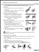
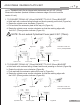
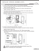
9. SECURING THE EXTERIOR ASSEMBLY TO THE DOOR
a. From the side marked “This side against
door”, route the Control Wire through the
rectangular slot in the Mounting Plate
(Figure 9a).
b. Place Mounting Plate against door with tailpiece passing
through the center hole in the three hole set (Figure9b).
c. Secure the Mounting Plate to the Exterior Assembly using
two 1-1/8” (28mm) Screws (Figure 9c).
d. Hand tighten with a Phillips Screwdriver leaving loosely connected (Figure 9d).
e. Check that the Rubber Gasket is properly aligned and correct as necessary
(Figure 9e).
f. Check vertical alignment of the lock (Figure 9f).
g. Tighten securely with a hand held Phillips Screwdriver. DO NOT OVER TIGHTEN
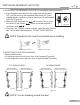
10. OPTIONAL INSTALLATION
a. Using a 1/16” (2mm) drill bit, drill a pilot hole in your door using the
Mounting Plate upper hole as a guide (Figure 10a).
b. Insert one 3/4” (19mm) screw and tighten.
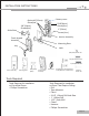
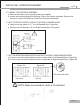
8. INSTALLING THE EXTERIOR ASSEMBLY
Work with the Door Open for easy access.
a. Unpack the Exterior Assembly. Use care to not scratch the green circuit board
during handling and installation.
b. Check that the Rubber Gasket is properly seated on the Exterior Assembly
(Figure 8a-b).
c. Insert the Exterior Assembly onto the door with the tailpiece going through the
Deadbolt Latch Set cross shaped spindle connector in the VERTICAL POSITION.
Route the Control Wire through the door under the Deadbolt Latch Set (Figure 8c).
NOTE: Tailpiece must be
positioned vertically
INSTALLING EXTERIOR ASSEMBLY
Figure 8a-b Figure 8c
Figure 10a
Figure 9a-f
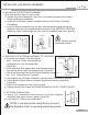
NOTE: Lock and unlock using the key to see if
the Deadbolt Latch is opening and closing easily.
Control Wire
Silicone Gasket
Latch Hole
Control
wire
Tail piece
(Vertical)
Mounting Plate
Right handed door view
Control wire
3/4”(19mm)screw
Optional Installation
Figure 9a-f