FMIx User Manual 2010 August V1.
Copyright 2010 August All Rights Reserved Manual Version 1.0c The information contained in this document is subject to change without notice. We make no warranty of any kind with regard to this material, including, but not limited to, the implied warranties of merchantability and fitness for a particular purpose. We shall not be liable for errors contained herein or for incidental or consequential damages in connection with the furnishing, performance, or use of this material.
International Standard Compliance Safety Authentication sign of Standard Ispe3ction Bureau for U.S.A. Complies with UL 60601-1 and CAN/CSA C22.2 NO. 601.1 CE MARK This device complies with the requirements of the EEC directive 89/336/EEC with regard to “Electromagnetic compatibility” and 73/23/EEC “Low Voltage Directive”. FCC This device complies with part 15 of the FCC rules. Operation is subject to the following two conditions: (1) This device may not cause harmful interference.
Safety Precautions General Safety Precautions Please ensure the following safety precautions are adhered to at all times. Follow the electrostatic precautions outlined below whenever the FMIx is opened. Do not apply voltage levels that exceed the specified voltage range. Doing so may cause fire and/or an electrical shock. Electric shocks can occur if the FMIx chassis is opened when the FMIx is running. Do not drop or insert any objects into the ventilation openings of the FMIx.
o o o o o Expose to strong magnetic or electrical fields. Expose to dirty or dusty environments Operate during a gas leak In a site where the ambient temperature exceeds the rated temperature Throw batteries in fires as they may explode, check local codes for special battery disposal instructions CAUTION ON LITHIUM BATTERIES There is a danger of explosion if the battery is replaced incorrectly. Replace only with the same or equivalent type recommended by the manufacturer.
Product Disposal Outside the European Union - If you wish to dispose of used electrical and electronic products outside the European Union, please contact your local authority so as to comply with the correct disposal method. Within the European Union: EU-wide legislation, as implemented in each Member State, requires that waste electrical and electronic products carrying the mark (left) must be disposed of separately from normal household waste.
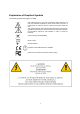
Explanation of Graphical Symbols The following symbol may appear on FMIx This symbol warns the user that un-insulated voltage within the unit may have sufficient magnitude to cause electric shock. Therefore, it is dangerous to make any kind of contact with any part inside this unit. This symbol alerts the user that important information concerning the operation and maintenance of this unit has been included. Therefore, the information should be read carefully in order to avoid any problems.
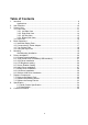
Table of Contents 1. 2. 3. 4. 5. 6. 7. 8. 9. Introduce ......................................................................................................................9 Applications...........................................................................................................9 Item Checklist ............................................................................................................10 System View ........................................................................
1. Introduce FM1x, an Intel Atom platform based WebPAD with 12.1” LCD, it provides two USB2 host ports, 10/100/1000 base-T RJ45 port, standard CRT port, headphone-out and Ext. Microphone-in jacks for I/O interface, Also contains 4 function keys for customized programming, built-in IEEE802.11b/g/n WLAN for wireless communication.
2. Item Checklist Take out the system unit from the carton. Remove the unit by carefully clutching the foam inserts and remove slowly to protect the system. The following contents should be found in the carton: a. System b. Medical Grade Power cord for US Standard c. Medical Power Adapter d. Stylus Pen f.
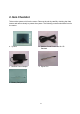
3. System View Refer to the pictures below to identify the components. 3.1.
16:10 Programmable Buttons LED Indicator 12
3.2.1.
3.2.2. Right Side View Power On/Off Button LAN Jack VGA Port USB Port x 2 Earphone Jack Ext.
3.2.3. Up Side View Bar Code Reader 3.2.4.
3.3.
4. Basic Operations This section helps you to start using your FM1X-A12. 4.1. Install the Battery Pack a. Insert the battery pack until it clicks into place. b. Slide both Battery Release tabs to the lock position. 4.2. Connect the AC Power Adapter IMPORTANT! Damage may occur if you use a different adapter to power the FMIx or use the FMIx’s adapter to power other electrical devices. You may damage both your battery pack(s) and the FMIX with a faulty AC-DC adapter.
4.3. Turn ON the FMIx a. Press the power button and release at the right side of the system. 4.4. Using the Stylus Pen IMPORTANT! DO NOT touch the screen with sharp objects or any other type of writing instrument. It can damage the screen. The FMIx has a touch-sensitive screen. It allows you to use your stylus pen or finger to interact with the device. With the FMIx, you can input data using the full screen area.
5. Mounting The FMIx Web PAD can be mounted onto the wall or stand. CAUTION: When mounting the monitor, take care to tighten the retention screws or bolts until fully secure, but do not over tighten. Over tightening the retention screws or bolts may cause them to become stripped, rendering them useless. Wall Mounting Installation The FMIx has Video Electronics Standards Association (VESA) standard mounting holes tapped into the rear panel.
6. Drivers Installation 6.1. Chipset Driver Installation a. Click the Setup.exe on the My Computer window. b. Click the “Next” button on the Setup window. c. Click the “Yes” button on the Setup window. d. Click the “Next” button on the Setup window.
e. Select “Yes, I want to restart my computer now” and click the “Finish” button on the Setup window. 6.2. Touch Panel Driver Installation(USB Interface) a. Click Setup.exe b.
Click the “Next” button Enable check box, and Click the “Next” button Click the “OK” button c.
Click the “OK” button Select “Setting for Touch Panel Calibration Click “+” to Calibrate touch panel” 23
6.3. VGA Driver Installation a. Click the “Setup.exe” on the My Computer window. Click the “Next” button on the Intel(R) Chipset Graphics Driver SoftwareInstallShield(R) Wizard window. Click the “Yes” button b.
c. Click the “Next” button d.
6.4. LCD Brightness setting Choose “Tablet & Pen settings” icon a. LCD Brightness setting 6.5. Screen Rotation Setting Choose “Intel chipset Graphics setting” icon b.
a.) Choose “Display setting b.) Enable Rotation setting 6.6. Audio Driver Installation a. Select “Setup.exe “ on Audio driver folder Finished. Select “Yes, I want to restart my computer now” and click the “Finish” button.
6.7. Button Driver Installation Select “Setup” on the My Computer window. Click the “Next” button on the Button Driver – InstallShield Wizard window. Click the “Install” button on the Button Driver – InstallShield Wizard window. Click the “Continue Anyway” button on the Hardware Installation window. Select “Yes, I want to restart my computer now” and click the “Finish” button.
6.7.1.
6.8. LAN Driver Installation a. Select “Setup.exe” on the My Computer window. b. Select “next” button on the My Computer window. c. Select “finish” button 6.9. Wireless LAN Driver Installation a. Click the “setup.exe” on the My Computer window. b.
c. Click the “Next” Button d. Click the “Next” button e. Click the “Next” button. f. Click the “Finish” button.
7. Replace Components 7.1. Remove the Battery Pack IMPORTANT! Never attempt to remove the battery pack while the FMIX is turned ON, as this may result in the loss of working data. a. Slide both battery release tabs to the unlock position. b. Pull the battery pack away from the body. 7.2. Replace the Memory Module IMPORTANT! DO NOT touch the golden contacts as this can damage the Ensure memory that the notches in the memory module line up with the DIMM slot keys. a. Remove the screw (1). b.
c. Remove the memory module from the slot. 7.3. Replace the Storage Device a. Remove the screws (2) that secure the HDD cover. b. Slide the HDD towards you. c. Disconnect the HDD cable carefully. d. Replace the 1.8” HDD.
8. Specification 8.1 Detail Product Specification Model Motherboard LCD & Touch FMIx CPU Intel Atom N270 @1.6GHz Core Logic Intel 945GSE SO-DIMM (DRR II) Standard 1GB, Max. 2GB VGA & Graphic Built-in Intel 945GSE LCD Size 12.1” TFT LCD, Normal LCD 4:3 Or 12.1” TFT LCD, Wide Screen LCD 16:10 Brightness Around 200 nits Resolution XGA 1024 x 768 , with CCFL BL Or WXGA 1280 x 800, with LED BL Storage & Expansion Input/Output Ports Indicators & Buttons Touch Type 12.
Power & Battery Bluetooth-Option Built-in V2.1 +EDR odule (USB) Power Adapter Cincon Electronics Co., LTD TR60M19 Input: 90 ~240Vac Output: DC19V, 3.15A Rechargeable Li-ion Battery Battery Pack (4S1P 14.
9. Contact Information MoBitS Electronic, Inc. Phone: +886-2-2603-9288 Fax: +886-2-2601-2877 World Wide Web: www.mo-bits.com Sales Email: sales@mo-bits.
Federal Communication Commission Interference Statement This equipment has been tested and found to comply with the limits for a Class B digital device, pursuant to Part 15 of the FCC Rules. These limits are designed to provide reasonable protection against harmful interference in a residential installation. This equipment generates, uses and can radiate radio frequency energy and, if not installed and used in accordance with the instructions, may cause harmful interference to radio communications.