
Technical data


USB and PS/2 Multimedia Keyboard Interface
USB and PS/2 Multimedia Keyboard Interface, Rev. 1
8 Freescale Semiconductor
1.4 Hardware Descriptions
MC68HC908JB8
8 x 18
Key Matrix
Scroll LED
Caps LED
Num LED
USB Plug
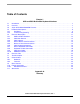
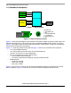
Figure 1-1. . Block Diagram
USB Plug
USB to PS/2
Converter
12
4
6
5
3
PS/2 Plug
6-pin PS/2 Plug
1 – Data (USB D– pin)
2 – NC
3 – Ground (USB Ground)
4 – +5V (USB +5V)
5 – Clock (USB D+ pin)
6 – NC
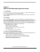
Figure 1-2. USB and PS/2 Connections
Figure 1-1 shows the block diagram of the keyboard. The solution includes the JB8, key button inputs and
LED indicator outputs only. The connections of the corresponding USB and PS/2 signals are shown in
Figure 1-2 The USB to PS/2 converter standard connections are the USB D– and D+ pins connected to
the PS/2 Data and Clock pins respectively.
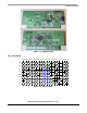
Figure 1-3. shows the printed circuit board and Figure 1-16 shows the schematic of the keyboard.
• J1 is used for USB connection
• J2 is used for PS/2 mouse connection (for future development)
• J3 and J7 are used for in-circuit programming
• 8 rows x 18 columns key matrix is implemented
– 8 rows implemented in PTA[7:0]
– 18 columns implemented in PTB[7:0], PTC[7:0], PTE0 and PTE2
• Keyboard LEDs
– Scroll Lock at PTD2
– Caps Lock at PTD3
– Num Lock at PTD4
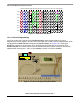
Figure 1-4 shows the key matrix for the 107 standard keyboard with power management keys (Power,
Wake and Sleep). Figure 1-5 shows the key matrix for multimedia keyboard with function key.