
Technical data
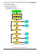
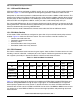
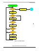
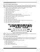
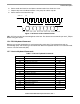
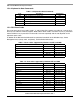
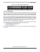
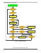
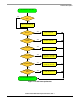
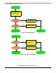

Table 1-6. Scan codes supported by Windows ME
Description Make Code Break Code
AC Calculator $E0, $2B $E0, $F0, $2B
AC Local Browser $E0, $40 $E0, $F0, $40
AC Consumer Control Configuration $E0, $50 $E0, $F0, $50
Firmware Description
USB and PS/2 Multimedia Keyboard Interface, Rev. 1
Freescale Semiconductor 17
1.5.10 USB Main Routine
Figure 1-11 shows the USB main routine. The routine scans the keyboard every 40 ms. If there are keys
pressed or released, it puts the key codes into a buffer and prepares the input reports for the keys through
endpoint 1 or endpoint 2. If the USB bus idles for more than 6
ms, the routine puts the MC68HC908JB8
into STOP mode until it detects a resume signal from the host or any key pressed for remote wake-up.
Figure 1-12 shows the USB interrupt routines. The USB engine automatically responds to a valid USB
token with either ACK, NAK, or STALL, depending on the registers setting, and ignores it if it is invalid.
The firmware has to set the registers for the USB engine to give a correct response to the token in different
stages. The USB interrupt will be executed whenever there is an EOP, resume signal from host, valid data
received or data transmitted. The USB interrupt routine also makes preparation for the next USB
transaction and handles any valid command or data received.
Figure 1-13 to Figure 1-15 show the routines of handling the Control Transfers. Control transfers have two
or three transaction stages: Setup, Data (optional) and Status as shown below:
• Control Write: SETUP, OUT, OUT, OUT... IN
• Control Read: SETUP, IN, IN, IN... OUT
• No Data Control: SETUP, IN
The firmware first distinguishes the kinds of control transfers and does the corresponding preparation for
the next stage.