
Technical data

USB and PS/2 Multimedia Keyboard Interface
USB and PS/2 Multimedia Keyboard Interface, Rev. 1
14 Freescale Semiconductor
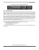
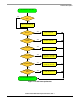
1.5.4 Host to Device Communications
Data sent from host to device is read while the clock line is high. In an idle state, both the Clock and the
Data lines are pulled high. The host starts sending data by pulling the Clock line low for a minimum of
100
ms. Figure 1-9 shows the signal diagram. Communications steps are shown as below:
1. Host waits until no auxiliary device transmission is in progress.
2. Host pulls the Clock line low.
3. Host pulls the Data line low as the start bit.
4. Host releases the Clock line.
5. Device pulls Clock line low.
6. Host sends out data.
7. Device releases the Clock line high and read Data.
8. Device reads the Clock line and aborts communication if the Clock line is low.
9. Repeat steps 5 to 7 for Data 1 to Data 7 and the parity bit.
10. Device pulls the Clock line low.
11. Host releases the Data line.
12. Device releases the Clock line high.
13. Device reads the Data line high for stop signal and sends error if the Data line is low.
14. Device pull the Data and the Clock lines low.
15. Device release the Clock and the Data lines.
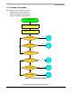
CLOCK
DATA
START DATA0 DATA1 DATA2 DATA3 DATA4 DATA5 DATA6 DATA7 PARITY STOP ACK
2
3
6
11,13
12STEP 1 4 7,8
9
10
14
15
5
Figure 1-9. Host to Device Communication
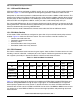
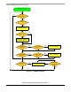
KBD_IN is the IRQ1 interrupt routine for receiving data from host. The interrupt is configured to execute
when a falling edge at the PTE4 (Data) pin is detected.
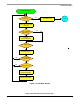
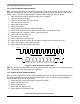
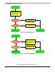
1.5.5 Device to Host Communications
Data sent from device to host is read at the falling edge of the clock. The device checks whether the host
is ready by detecting the clock high before transmitting data.
Figure 1-10 shows the signal diagram.
Communications steps are shown as below:
1. Device waits for the Clock line high for a minimum of 50 ms.
2. Abort if the Data line is low.
3. Device sends out data.
4. Device pulls the Clock line low.
5. Device releases the Clock line high.